T5743
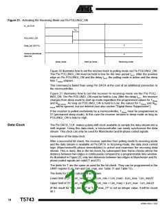
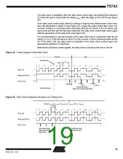
The data clock is available, after the data clock control logic has detected the distance
2T (Start bit) and is issued with the delay tDelay after the edge on Pin DATA (see figure
22).
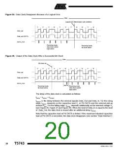
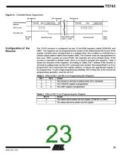
If the data clock control logic detects a timing or logical error (Manchester code viola-
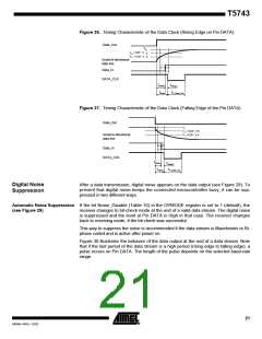
tion), like illustrated in Figure 23 and Figure 24, it stops the output of the data clock. The
receiver remains in receiving mode and starts with the bit check. If the bit check was
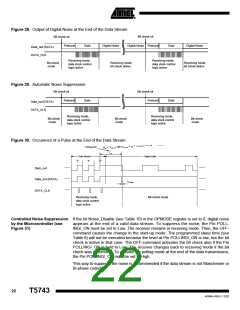
successful and the start bit has been detected, the data clock control logic starts again
with the generation of the data clock (see Figure 25).
It is recommended to use the function of the data clock only in conjunction with the bit
check 3, 6 or 9. If the bit check is set to 0 or the receiver is set to receiving mode via the
Pin POLLING/_ON, the data clock is available if the data clock control logic has
detected the distance 2T (Start bit).
Note that for Bi-phase-coded signals, the data clock is issued at the end of the bit.
Figure 22. Timing Diagram of the Data Clock
Preburst
'1'
Data
'0'
Bit check ok
T
2T
'1'
'1'
'1'
'1'
'0'
'1'
'1'
'1'
'0'
Dem_out
Data_out (DATA)
DATA_CLK
Start bit
tDelay
Receiving mode,
data clock control logic active
tP_Data_Clk
Bit-check mode
Figure 23. Data Clock Disappears Because of a Timing Error
Data
Timing error
(Tee < TLim_min OR TLim_max<Tee < TLim_min_2T OR Tee> TLim_max_2T
)
Tee
'1'
'1'
'1'
'1'
'1'
'0'
'1'
'1'
'0'
'1'
'0'
Dem_out
Data_out (DATA)
DATA_CLK
Receiving mode,
data clock control
logic active
Receiving mode,
bit check active
19
4569A–RKE–12/02

 ATMEL [ ATMEL ]