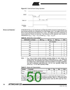
Figure 26. External Reset During Operation
CC
Brown-out Detection
AT90CAN128 has an On-chip Brown-out Detection (BOD) circuit for monitoring the VCC
level during operation by comparing it to a fixed trigger level. The trigger level for the
BOD can be selected by the BODLEVEL Fuses. The trigger level has a hysteresis to
ensure spike free Brown-out Detection. The hysteresis on the detection level should be
interpreted as VBOT+ = VBOT + VHYST/2 and VBOT- = VBOT - VHYST/2.
Table 20. BODLEVEL Fuse Coding(1)
BODLEVEL 2..0 Fuses
Min VBOT
Typ VBOT
Max VBOT
Units
111
110
101
100
011
010
001
000
BOD Disabled
4.1
4.0
3.9
3.8
2.7
2.6
2.5
V
V
V
V
V
V
V
Notes: 1. VBOT may be below nominal minimum operating voltage for some devices. For
devices where this is the case, the device is tested down to VCC = VBOT during the
production test. This guarantees that a Brown-Out Reset will occur before VCC drops
to a voltage where correct operation of the microcontroller is no longer guaranteed.
The test is performed using BODLEVEL = 010 for Low Operating Voltage and
BODLEVEL = 101 for High Operating Voltage .
Table 21. Brown-out Characteristics
Symbol
VHYST
tBOD
Parameter
Min.
Typ.
70
2
Max.
Units
mV
Brown-out Detector Hysteresis
Min Pulse Width on Brown-out Reset
µs
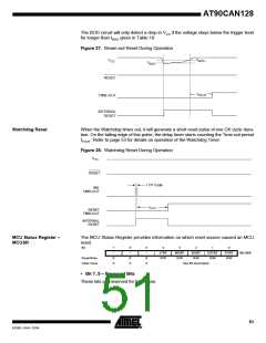
When the BOD is enabled, and VCC decreases to a value below the trigger level (VBOT-
in Figure 27), the Brown-out Reset is immediately activated. When VCC increases above
the trigger level (VBOT+ in Figure 27), the delay counter starts the MCU after the Time-
out period tTOUT has expired.
50
AT90CAN128
4250E–CAN–12/04

 ATMEL [ ATMEL ]