ATmega64A
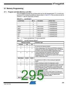
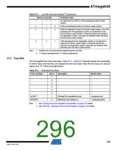
Table 27-2. Lock Bit Protection Modes(2) (Continued)
Memory Lock Bits
Protection Type
1
1
1
No restrictions for SPM or LPM accessing the Boot Loader
section.
2
3
1
0
0
0
SPM is not allowed to write to the Boot Loader section.
SPM is not allowed to write to the Boot Loader section, and LPM
executing from the Application section is not allowed to read
from the Boot Loader section. If Interrupt Vectors are placed in
the Application section, interrupts are disabled while executing
from the Boot Loader section.
4
0
1
LPM executing from the Application section is not allowed to
read from the Boot Loader section. If Interrupt Vectors are
placed in the Application section, interrupts are disabled while
executing from the Boot Loader section.
Note:
1. Program the Fuse bits before programming the Lock bits.
2. “1” means unprogrammed, “0” means programmed
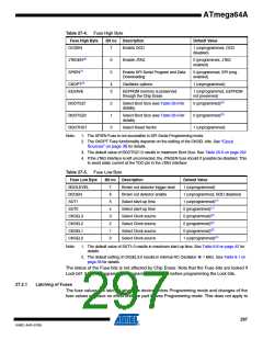
27.2 Fuse Bits
The ATmega64A has three fuse bytes. Table 27-3 - Table 27-5 describe briefly the functionality
of all the fuses and how they are mapped into the fuse bytes. Note that the fuses are read as
logical zero, “0”, if they are programmed.
Table 27-3. Extended Fuse Byte
Fuse Low Byte
Bit no
Description
Default Value
–
7
6
5
4
3
2
1
0
–
1
–
–
1
–
–
1
–
–
1
–
–
1
–
–
1
M103C(1)
WDTON(2)
ATmega103 compatibility mode
Watchdog Timer always on
0 (programmed)
1 (unprogrammed)
Note:
1. See “ATmega103 and ATmega64A Compatibility” on page 4 for details.
2. See “WDTCR – Watchdog Timer Control Register” on page 57 for details.
296
8160C–AVR–07/09

 ATMEL [ ATMEL ]