ATmega48/88/168
Reading the Fuse and Lock
Bits
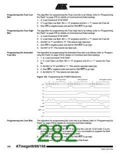
The algorithm for reading the Fuse and Lock bits is as follows (refer to “Programming
the Flash” on page 278 for details on Command loading):
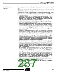
1. A: Load Command “0000 0100”.
2. Set OE to “0”, BS2 to “0” and BS1 to “0”. The status of the Fuse Low bits can
now be read at DATA (“0” means programmed).
3. Set OE to “0”, BS2 to “1” and BS1 to “1”. The status of the Fuse High bits can
now be read at DATA (“0” means programmed).
4. Set OE to “0”, BS2 to “1”, and BS1 to “0”. The status of the Extended Fuse bits
can now be read at DATA (“0” means programmed).
5. Set OE to “0”, BS2 to “0” and BS1 to “1”. The status of the Lock bits can now be
read at DATA (“0” means programmed).
6. Set OE to “1”.
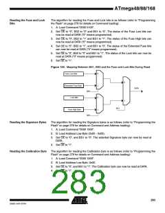
Figure 124. Mapping Between BS1, BS2 and the Fuse and Lock Bits During Read
0
Fuse Low Byte
Extended Fuse Byte
Lock Bits
0
1
1
0
DATA
BS2
BS1
Fuse High Byte
1
BS2
Reading the Signature Bytes
The algorithm for reading the Signature bytes is as follows (refer to “Programming the
Flash” on page 278 for details on Command and Address loading):
1. A: Load Command “0000 1000”.
2. B: Load Address Low Byte (0x00 - 0x02).
3. Set OE to “0”, and BS1 to “0”. The selected Signature byte can now be read at
DATA.
4. Set OE to “1”.
Reading the Calibration Byte
The algorithm for reading the Calibration byte is as follows (refer to “Programming the
Flash” on page 278 for details on Command and Address loading):
1. A: Load Command “0000 1000”.
2. B: Load Address Low Byte, 0x00.
3. Set OE to “0”, and BS1 to “1”. The Calibration byte can now be read at DATA.
4. Set OE to “1”.
283
2545D–AVR–07/04

 ATMEL [ ATMEL ]