Programming the Fuse Low
Bits
The algorithm for programming the Fuse Low bits is as follows (refer to “Programming
the Flash” on page 278 for details on Command and Data loading):
1. A: Load Command “0100 0000”.
2. C: Load Data Low Byte. Bit n = “0” programs and bit n = “1” erases the Fuse bit.
3. Give WR a negative pulse and wait for RDY/BSY to go high.
Programming the Fuse High
Bits
The algorithm for programming the Fuse High bits is as follows (refer to “Programming
the Flash” on page 278 for details on Command and Data loading):
1. A: Load Command “0100 0000”.
2. C: Load Data Low Byte. Bit n = “0” programs and bit n = “1” erases the Fuse bit.
3. Set BS1 to “1” and BS2 to “0”. This selects high data byte.
4. Give WR a negative pulse and wait for RDY/BSY to go high.
5. Set BS1 to “0”. This selects low data byte.
Programming the Extended
Fuse Bits
The algorithm for programming the Extended Fuse bits is as follows (refer to “Program-
ming the Flash” on page 278 for details on Command and Data loading):
1. 1. A: Load Command “0100 0000”.
2. 2. C: Load Data Low Byte. Bit n = “0” programs and bit n = “1” erases the Fuse
bit.
3. 3. Set BS1 to “0” and BS2 to “1”. This selects extended data byte.
4. 4. Give WR a negative pulse and wait for RDY/BSY to go high.
5. 5. Set BS2 to “0”. This selects low data byte.
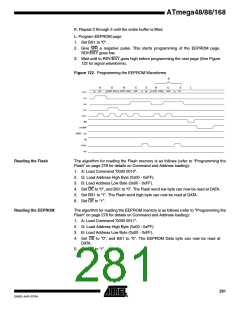
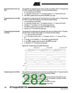
Figure 123. Programming the FUSES Waveforms
Write Fuse Low byte
Write Fuse high byte
Write Extended Fuse byte
A
C
A
C
A
C
0x40
DATA
XX
0x40
DATA
XX
0x40
DATA
XX
DATA
XA1
XA0
BS1
BS2
XTAL1
WR
RDY/BSY
RESET +12V
OE
PAGEL
Programming the Lock Bits
The algorithm for programming the Lock bits is as follows (refer to “Programming the
Flash” on page 278 for details on Command and Data loading):
1. A: Load Command “0010 0000”.
2. C: Load Data Low Byte. Bit n = “0” programs the Lock bit. If LB mode 3 is pro-
grammed (LB1 and LB2 is programmed), it is not possible to program the Boot
Lock bits by any External Programming mode.
3. Give WR a negative pulse and wait for RDY/BSY to go high.
The Lock bits can only be cleared by executing Chip Erase.
282
ATmega48/88/168
2545D–AVR–07/04

 ATMEL [ ATMEL ]