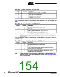
Table 16-3. Compare Output Mode, non-PWM Mode
COM2A1
COM2A0
Description
0
0
1
1
0
1
0
1
Normal port operation, OC2A disconnected.
Toggle OC2A on compare match.
Clear OC2A on compare match.
Set OC2A on compare match.
Table 16-4 shows the COM2A1:0 bit functionality when the WGM21:0 bits are set to fast PWM
mode.
Table 16-4. Compare Output Mode, Fast PWM Mode(1)
COM2A1
COM2A0
Description
0
0
1
1
0
1
0
1
Normal port operation, OC2A disconnected.
Reserved
Clear OC2A on compare match, set OC2A at TOP.
Set OC2A on compare match, clear OC2A at TOP.
Note:
1. A special case occurs when OCR2A equals TOP and COM2A1 is set. In this case, the com-
pare match is ignored, but the set or clear is done at TOP. See ”Fast PWM Mode” on page 144
for more details.
Table 16-5 shows the COM2A1:0 bit functionality when the WGM21:0 bits are set to phase cor-
rect PWM mode.
Table 16-5. Compare Output Mode, Phase Correct PWM Mode(1)
COM2A1
COM2A0
Description
0
0
0
1
Normal port operation, OC2A disconnected.
Reserved
Clear OC2A on compare match when up-counting. Set OC2A on
compare match when downcounting.
1
1
0
1
Set OC2A on compare match when up-counting. Clear OC2A on
compare match when downcounting.
Note:
1. A special case occurs when OCR2A equals TOP and COM2A1 is set. In this case, the com-
pare match is ignored, but the set or clear is done at TOP. See ”Phase Correct PWM Mode” on
page 146 for more details.
154
ATmega169P
8018A–AVR–03/06

 ATMEL [ ATMEL ]