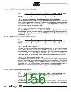
16.10.4 TIMSK2 – Timer/Counter2 Interrupt Mask Register
Bit
7
–
6
–
5
–
4
–
3
–
2
–
1
OCIE2A
R/W
0
0
TOIE2
R/W
0
(0x70)
TIMSK2
Read/Write
Initial Value
R
0
R
0
R
0
R
0
R
0
R
0
• Bit 1 – OCIE2A: Timer/Counter2 Output Compare Match A Interrupt Enable
When the OCIE2A bit is written to one and the I-bit in the Status Register is set (one), the
Timer/Counter2 Compare Match A interrupt is enabled. The corresponding interrupt is executed
if a compare match in Timer/Counter2 occurs, i.e., when the OCF2A bit is set in the
Timer/Counter 2 Interrupt Flag Register – TIFR2.
• Bit 0 – TOIE2: Timer/Counter2 Overflow Interrupt Enable
When the TOIE2 bit is written to one and the I-bit in the Status Register is set (one), the
Timer/Counter2 Overflow interrupt is enabled. The corresponding interrupt is executed if an
overflow in Timer/Counter2 occurs, i.e., when the TOV2 bit is set in the Timer/Counter2 Interrupt
Flag Register – TIFR2.
16.10.5 TIFR2 – Timer/Counter2 Interrupt Flag Register
Bit
0x17 (0x37)
7
6
5
–
4
–
3
–
2
–
1
OCF2A
R/W
0
0
TOV2
R/W
0
–
–
TIFR2
Read/Write
Initial Value
R
0
R
0
R
0
R
0
R
0
R
0
• Bit 1 – OCF2A: Output Compare Flag 2 A
The OCF2A bit is set (one) when a compare match occurs between the Timer/Counter2 and the
data in OCR2A – Output Compare Register2. OCF2A is cleared by hardware when executing
the corresponding interrupt handling vector. Alternatively, OCF2A is cleared by writing a logic
one to the flag. When the I-bit in SREG, OCIE2A (Timer/Counter2 Compare match Interrupt
Enable), and OCF2A are set (one), the Timer/Counter2 Compare match Interrupt is executed.
• Bit 0 – TOV2: Timer/Counter2 Overflow Flag
The TOV2 bit is set (one) when an overflow occurs in Timer/Counter2. TOV2 is cleared by hard-
ware when executing the corresponding interrupt handling vector. Alternatively, TOV2 is cleared
by writing a logic one to the flag. When the SREG I-bit, TOIE2A (Timer/Counter2 Overflow Inter-
rupt Enable), and TOV2 are set (one), the Timer/Counter2 Overflow interrupt is executed. In
PWM mode, this bit is set when Timer/Counter2 changes counting direction at 0x00.
16.10.6 ASSR – Asynchronous Status Register
Bit
(0xB6)
7
6
5
–
4
EXCLK
R/W
0
3
2
1
0
–
–
AS2
R/W
0
TCN2UB
OCR2UB
TCR2UB
ASSR
Read/Write
Initial Value
R
0
R
0
R
0
R
0
R
0
R
0
• Bit 4 – EXCLK: Enable External Clock Input
When EXCLK is written to one, and asynchronous clock is selected, the external clock input
buffer is enabled and an external clock can be input on Timer Oscillator 1 (TOSC1) pin instead
156
ATmega169P
8018A–AVR–03/06

 ATMEL [ ATMEL ]