AT90PWM2/3/2B/3B
that there are no unread data in the receive buffer. Note that the TXC flag must be cleared
before each transmission (before UDR is written) if it is used for this purpose.
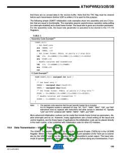
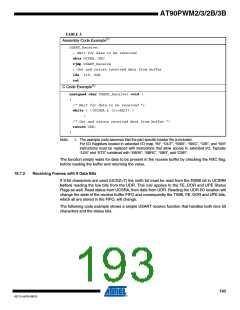
The following simple USART initialization code examples show one assembly and one C func-
tion that are equal in functionality. The examples assume asynchronous operation using polling
(no interrupts enabled) and a fixed frame format. The baud rate is given as a function parameter.
For the assembly code, the baud rate parameter is assumed to be stored in the r17:r16
Registers.
TABLE 2.
Assembly Code Example(1)
USART_Init:
; Set baud rate
sts UBRRH, r17
sts UBRRL, r16
; Set frame format: 8data, no parity & 2 stop bits
ldi r16, (0<<UMSEL)|(0<<UPM0)|(1<<USBS)|(3<<UCSZ0)
sts UCSRC,r16
; Enable receiver and transmitter
ldi r16, (1<<RXEN0)|(1<<TXEN0)
sts UCSRB,r16
ret
C Code Example(1)
void USART_Init( unsigned int baud )
{
/* Set baud rate */
UBRRH = (unsigned char)(baud>>8);
UBRRL = (unsigned char)baud;
/* Set frame format: 8data, no parity & 2 stop bits */
UCSRC = (0<<UMSEL)|(0<<UPM0)|(1<<USBS)|(3<<UCSZ0);
/* Enable receiver and transmitter */
UCSRB = (1<<RXEN0)|(1<<TXEN0);
}
Note:
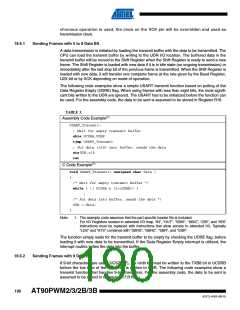
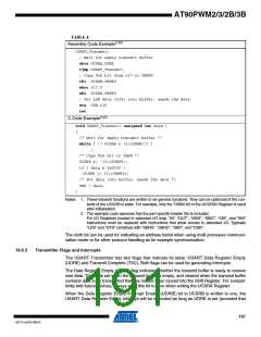
1. The example code assumes that the part specific header file is included.
For I/O Registers located in extended I/O map, “IN”, “OUT”, “SBIS”, “SBIC”, “CBI”, and “SBI”
instructions must be replaced with instructions that allow access to extended I/O. Typically
“LDS” and “STS” combined with “SBRS”, “SBRC”, “SBR”, and “CBR”.
More advanced initialization routines can be made that include frame format as parameters, dis-
able interrupts and so on. However, many applications use a fixed setting of the baud and
control registers, and for these types of applications the initialization code can be placed directly
in the main routine, or be combined with initialization code for other I/O modules.
18.6 Data Transmission – USART Transmitter
The USART Transmitter is enabled by setting the Transmit Enable (TXEN) bit in the UCSRB
Register. When the Transmitter is enabled, the normal port operation of the TxDn pin is overrid-
den by the USART and given the function as the Transmitter’s serial output. The baud rate,
mode of operation and frame format must be set up once before doing any transmissions. If syn-
189
4317J–AVR–08/10

 ATMEL [ ATMEL ]