AT90PWM2/3/2B/3B
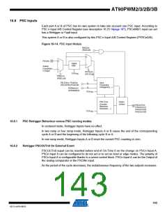
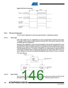
16.8 PSC Inputs
Each part A or B of PSC has its own system to take into account one PSC input. According to
PSC n Input A/B Control Register (see description 16.25.14page 167), PSCnIN0/1 input can act
has a Retrigger or Fault input.
This system A or B is also configured by this PSC n Input A/B Control Register (PFRCnA/B).
Figure 16-14. PSC Input Module
PAOCnA
(PAOCnB)
0
PSCINn
0
1
Digital
Filter
1
Analog
Comparator
n Output
PFLTEnA
(PFLTEnB)
CLK
PSC
PISELnA
(PISELnB)
PELEVnA / PCAEnA
(PELEVnB)(PCAEnB)
Input
Processing
(retriggering ...)
2
4
PRFMnA3:0
(PRFMnB3:0)
CLK
PSC
PSC Core
(Counter,
Waveform
Generator, ...)
Output
Control
PSCOUTn0
(PSCOUTn1)
(PSCOUT22)
(PSCOUT23)
CLK
PSC
16.8.1
16.8.2
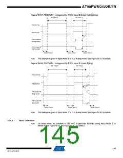
PSC Retrigger Behaviour versus PSC running modes
In centered mode, Retrigger Inputs have no effect.
In two ramp or four ramp mode, Retrigger Inputs A or B cause the end of the corresponding
cycle A or B and the beginning of the following cycle B or A.
In one ramp mode, Retrigger Inputs A or B reset the current PSC counting to zero.
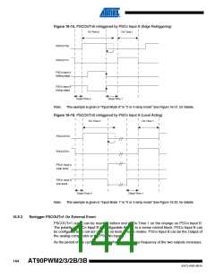
Retrigger PSCOUTn0 On External Event
PSCOUTn0 ouput can be resetted before end of On-Time 0 on the change on PSCn Input A.
PSCn Input A can be configured to do not act or to act on level or edge modes. The polarity of
PSCn Input A is configurable thanks to a sense control block. PSCn Input A can be the Output of
the analog comparator or the PSCINn input.
As the period of the cycle decreases, the instantaneous frequency of the two outputs increases.
143
4317J–AVR–08/10

 ATMEL [ ATMEL ]