16.7.2
Modes of Operation
16.7.2.1
Normal Mode
The simplest mode of operation is the normal mode. See Figure 16-6.
The active time of PSCOUTn0 is given by the OT0 value. The active time of PSCOUTn1 is given
by the OT1 value. Both of them are 12 bit values. Thanks to DT0 & DT1 to ajust the dead time
between PSCOUTn0 and PSCOUTn1 active signals.
The waveform frequency is defined by the following equation:
f
1
CLK_PSCn
f
= ----------------------------- = ---------------------------------------------------------------------- =
= 1
PSCn
PSCnCycle
(OT0 + OT1 + DT0 + DT1)
16.7.2.2
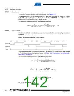
Enhanced Mode
The Enhanced Mode uses the previously described method to generate a high resolution
frequency.
Figure 16-13. Enhanced Mode, Timing Diagram
DT1
DT0
OT0
DT1
OT1
DT0
DT0
OT1+1
OT0
PSCOUTn0
PSCOUTn1
Period
T2
T1
The supplementary step in counting to generate fb2 is added on the PSCn0 signal while needed
in the frame according to the fractional divider. SeeTable 16-5, “Distribution of fb2 in the modu-
lated frame,” on page 141.
The waveform frequency is defined by the following equations:
f
1
CLK_PSCn
f1
= ----- = ----------------------------------------------------------------------
PSCn
T
(OT0 + OT1 + DT0 + DT1)
1
f
1
CLK_PSCn
f2
= ----- = --------------------------------------------------------------------------------
PSCn
T
(OT0 + OT1 + DT0 + DT1 + 1)
2
d
16
16 – d
16
------
---------------
× f2PSCn
fAVERAGE
=
× f1PSCn
+
d is the fractionel divider factor.
142
AT90PWM2/3/2B/3B
4317J–AVR–08/10

 ATMEL [ ATMEL ]