AT90PWM2/3/2B/3B
If PELEVnx bit set, the significant edge of PSCn Input A or B is rising (edge modes) or the active
level is high (level modes) and vice versa for unset/falling/low
- In 2- or 4-ramp mode, PSCn Input A is taken into account only during Dead-Time0 and On-
Time0 period (respectively Dead-Time1 and On-Time1 for PSCn Input B).
- In 1-ramp-mode PSC Input A or PSC Input B act on the whole ramp.
16.8.4.3
Input Mode Operation
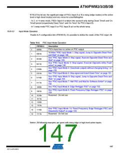
Thanks to 4 configuration bits (PRFM3:0), it’s possible to define the mode of the PSC input. All
Table 16-6. PSC Input Mode Operation
PRFM3:0
Description
PSCn Input has no action on PSC output
0
1
0000b
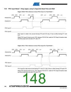
16.9See “PSC Input Mode 1: Stop signal, Jump to Opposite Dead-Time
and Wait” on page 148.
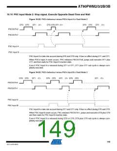
See “PSC Input Mode 2: Stop signal, Execute Opposite Dead-Time and
Wait” on page 149.
0001b
0010b
0011b
2
3
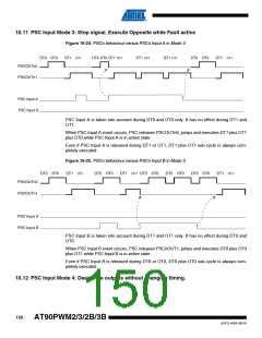
See “PSC Input Mode 3: Stop signal, Execute Opposite while Fault
active” on page 150.
See “PSC Input Mode 4: Deactivate outputs without changing timing.” on
page 150.
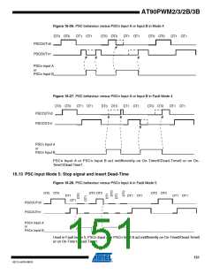
See “PSC Input Mode 5: Stop signal and Insert Dead-Time” on page 151.
4
5
6
0100b
0101b
0110b
See “PSC Input Mode 6: Stop signal, Jump to Opposite Dead-Time and
Wait.” on page 152.
See “PSC Input Mode 7: Halt PSC and Wait for Software Action” on page
152.
See “PSC Input Mode 8: Edge Retrigger PSC” on page 152.
7
8
9
0111b
1000b
1001b
See “PSC Input Mode 9: Fixed Frequency Edge Retrigger PSC” on page
153.
Reserved : Do not use
10
11
12
13
1010b
1011b
1100b
1101b
See “PSC Input Mode 14: Fixed Frequency Edge Retrigger PSC and
Disactivate Output” on page 154.
Reserved : Do not use
14
15
1110b
1111b
Notice: All following examples are given with rising edge or high level active inputs.
147
4317J–AVR–08/10

 ATMEL [ ATMEL ]