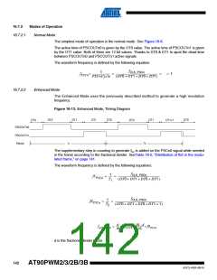
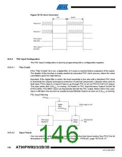
Figure 16-19. Burst Generation
OFF
BURST
PSCOUTn0
PSCOUTn1
PSCn Input A
(high level)
PSCn Input A
(low level)
16.8.4
PSC Input Configuration
The PSC Input Configuration is done by programming bits in configuration registers.
16.8.4.1
Filter Enable
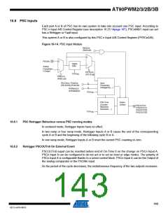
If the “Filter Enable” bit is set, a digital filter of 4 cycles is inserted before evaluation of the signal.
The disable of this function is mainly needed for prescaled PSC clock sources, where the noise
cancellation gives too high latency.
Important: If the digital filter is active, the level sensitivity is true also with a disturbed PSC clock
to deactivate the outputs (emergency protection of external component). Likewise when used as
fault input, PSCn Input A or Input B have to go through PSC to act on PSCOUTn0/1/2/3 output.
This way needs that CLKPSC is running. So thanks to PSC Asynchronous Output Control bit
(PAOCnA/B), PSCnIN0/1 input can desactivate directly the PSC output. Notice that in this case,
input is still taken into account as usually by Input Module System as soon as CLKPSC is running.
PSC Input Filterring
CLK
PSC
Digital
Filter
PSCn Input A or B
4 x CLK
PSC
PSC Input
Module X
Ouput
Stage
PSCOUTnX
PIN
16.8.4.2
Signal Polarity
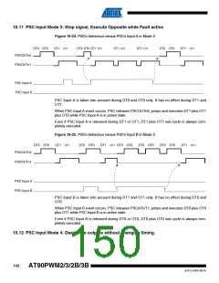
One can select the active edge (edge modes) or the active level (level modes) See PELEVnx bit
description in Section “PSC n Input A Control Register – PFRCnA”, page 16716.25.14.
146
AT90PWM2/3/2B/3B
4317J–AVR–08/10

 ATMEL [ ATMEL ]