AT90USB64/128
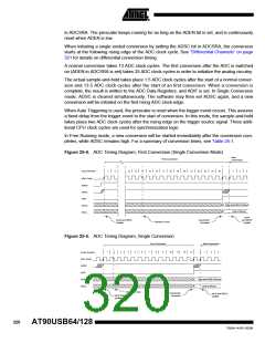
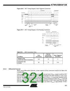
Figure 25-6. ADC Timing Diagram, Auto Triggered Conversion
One Conversion
Next Conversion
1
2
3
4
5
6
7
8
9
10
11
12
13
1
2
Cycle Number
ADC Clock
Trigger
Source
ADATE
ADIF
ADCH
ADCL
Sign and MSB of Result
LSB of Result
Sample &
Hold
Prescaler
Reset
Conversion
Complete
Prescaler
Reset
MUX and REFS
Update
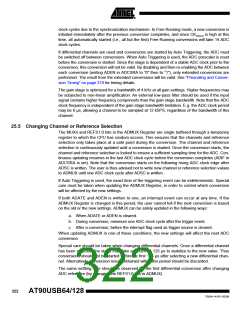
Figure 25-7. ADC Timing Diagram, Free Running Conversion
One Conversion
Next Conversion
11
12
13
1
2
3
4
Cycle Number
ADC Clock
ADSC
ADIF
ADCH
ADCL
Sign and MSB of Result
LSB of Result
Sample & Hold
Conversion
Complete
MUX and REFS
Update
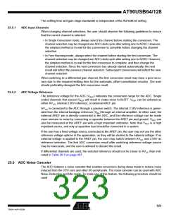
Table 25-1. ADC Conversion Time
Normal
First
Conversion
Conversion,
Single Ended
Auto Triggered
Convertion
Condition
Sample & Hold
(Cycles from Start of Convertion)
14.5
1.5
13
2
Conversion Time
(Cycles)
25
13.5
25.4.1
Differential Channels
When using differential channels, certain aspects of the conversion need to be taken into
consideration.
Differential conversions are synchronized to the internal clock CKADC2 equal to half the ADC
clock frequency. This synchronization is done automatically by the ADC interface in such a way
that the sample-and-hold occurs at a specific phase of CKADC2. A conversion initiated by the
user (i.e., all single conversions, and the first free running conversion) when CKADC2 is low will
take the same amount of time as a single ended conversion (13 ADC clock cycles from the next
prescaled clock cycle). A conversion initiated by the user when CKADC2 is high will take 14 ADC
321
7593A–AVR–02/06

 ATMEL [ ATMEL ]