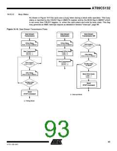
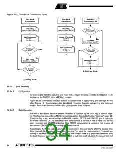
Figure 16-17. Data Block Transmission Flows
Data Block
Data Block
Data Block
Transmission
Initialization
Transmission ISR
FIFOs Filling
Write 16 Data to MMDAT
FIFOs Filling
Write 16 Data to MMDAT
FIFO Empty?
F1EI or F2EI = 1?
Start Transmission
DATEN = 1
DATEN = 0
Unmask FIFOs Empty
F1EM = 0
F2EM = 0
FIFO Filling
Write 8 Data to MMDAT
Start Transmission
DATEN = 1
DATEN = 0
FIFO Empty?
F1EI or F2EI = 1?
No More Data
To Send?
FIFO Filling
Write 8 Data to MMDAT
Mask FIFOs Empty
F1EM = 1
F2EM = 1
No More Data
to Send?
b. Interrupt Mode
a. Polling Mode
16.6.4
Data Receiver
16.6.4.1
Configuration
To receive data from the card, the user must first configure the data controller in reception mode
by clearing the DATDIR bit in MMCON1 register.
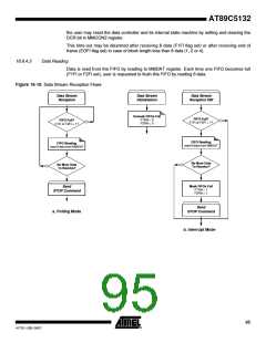
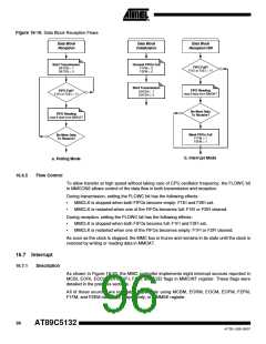
Figure 16-18 summarizes the data stream reception flows in both polling and interrupt modes
while Figure 16-19 summarizes the data block reception flows in both polling and interrupt
modes, these flows assume that block length is greater than 16 Bytes.
16.6.4.2
Data Reception
The end of data frame (block or stream) reception is signalled by the EOFI flag in MMINT regis-
ter. This flag may generate an MMC interrupt request as detailed in Section "Interrupt", page 96.
When this flag is set, two other flags in MMSTA register: DATFS and CRC16S give a status on
the frame received. DATFS indicates if the frame format is correct or not: a valid End bit has
been received, and CRC16S indicates if the CRC16 computation is correct or not. In case of
data stream CRC16S has no meaning and stays cleared.
According to the MMC specification data transmission, the card starts after the access time
delay (formally NAC parameter) beginning from the End bit of the read command. To avoid any
locking of the MMC controller when card does not send its data (e.g. physically removed from
the bus), the user must launch a time-out period to exit from such situation. In case of time-out
94
AT89C5132
4173E–USB–09/07

 ATMEL [ ATMEL ]