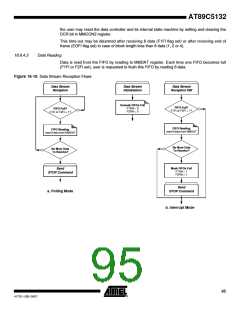
Figure 16-19. Data Block Reception Flows
Data Block
Reception
Data Block
Data Block
Initialization
Reception ISR
Start Transmission
DATEN = 1
DATEN = 0
Unmask FIFOs Full
F1FM = 0
F2FM = 0
FIFO Full?
F1EI or F2EI = 1?
Start Transmission
DATEN = 1
DATEN = 0
FIFO Reading
read 8 data from MMDAT
FIFO Full?
F1EI or F2EI = 1?
No More Data
To Receive?
FIFO Reading
read 8 data from MMDAT
Mask FIFOs Full
F1FM = 1
F2FM = 1
No More Data
To Receive?
b. Interrupt Mode
a. Polling Mode
16.6.5
Flow Control
To allow transfer at high speed without taking care of CPU oscillator frequency, the FLOWC bit
in MMCON2 allows control of the data flow in both transmission and reception.
During transmission, setting the FLOWC bit has the following effects:
•
•
MMCLK is stopped when both FIFOs become empty: F1EI and F2EI set.
MMCLK is restarted when one of the FIFOs becomes full: F1EI or F2EI cleared.
During reception, setting the FLOWC bit has the following effects:
•
•
MMCLK is stopped when both FIFOs become full: F1FI and F2FI set.
MMCLK is restarted when one of the FIFOs becomes empty: F1FI or F2FI cleared.
As soon as the clock is stopped, the MMC bus is frozen and remains in its state until the clock is
restored by writing or reading data in MMDAT.
16.7 Interrupt
16.7.1
Description
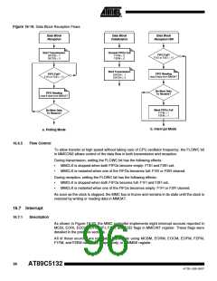
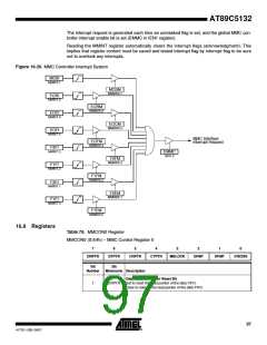
As shown in Figure 16-20, the MMC controller implements eight interrupt sources reported in
MCBI, EORI, EOCI, EOFI, F2FI, F1FI, and F2EI flags in MMCINT register. These flags were
detailed in the previous sections.
All of these sources are maskable separately using MCBM, EORM, EOCM, EOFM, F2FM,
F1FM, and F2EM mask bits, respectively, in MMMSK register.
96
AT89C5132
4173E–USB–09/07

 ATMEL [ ATMEL ]