AT89C5132
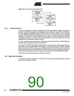
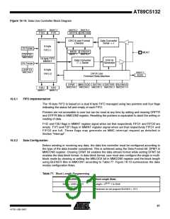
Figure 16-14. Data Line Controller Block Diagram
MMINT.0
MMINT.2
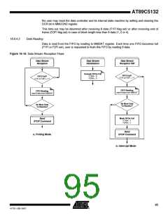
MMSTA.3
MMSTA.4
F1EI
F1FI
DATFS CRC16S
CRC16 and Format
Checker
Data Converter
Serial -> //
8-byte
TX Pointer
FIFO 1
MCBI
MMINT.1
CBUSY
MMSTA.5
MDAT
DTPTR
MMCON0.6
16-byte FIFO
MMDAT
Data Converter
// -> Serial
CRC16
Generator
RX Pointer
DRPTR
MMCON0.7
8-byte
MMINT.4
DATA Line
Finished State Machine
FIFO 2
EOFI
DFMT MBLOCK DATEN DATDIR BLEN3:0
MMCON0.2 MMCON0.3 MMCON1.2 MMCON1.3 MMCON1.7:4
F2EI
MMINT.1
F2FI
MMINT.3
16.6.1
FIFO Implementation
The 16-byte FIFO is based on a dual 8-byte FIFO managed using two pointers and four flags
indicating the status full and empty of each FIFO.
Pointers are not accessible to user but can be reset at any time by setting and clearing DRPTR
and DTPTR Bits in MMCON0 register. Resetting the pointers is equivalent to abort the writing or
reading of data.
F1EI and F2EI flags in MMINT register signal when set that respectively FIFO1 and FIFO2 are
empty. F1FI and F2FI flags in MMINT register signal when set that respectively FIFO1 and
FIFO2 are full. These flags may generate an MMC interrupt request as detailed in
Section “Interrupt”.
16.6.2
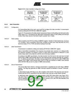
Data Configuration
Before sending or receiving any data, the data line controller must be configured according to
the type of the data transfer considered. This is achieved using the Data Format bit: DFMT in
MMCON0 register. Clearing DFMT bit enables the data stream format while setting DFMT bit
enables the data block format. In data block format, user must also configure the single or multi-
block mode by clearing or setting the MBLOCK bit in MMCON0 register and the block length
using BLEN3:0 Bits in MMCON1 according to Table 77. Figure 16-15 summarizes the data
modes configuration flows.
Table 77. Block Length Programming
BLEN3:0
BLEN = 0000 to 1011
> 1011
Block Length (Byte)
Length = 2BLEN: 1 to 2048
Reserved: do not program BLEN3:0 > 1011
91
4173E–USB–09/07

 ATMEL [ ATMEL ]