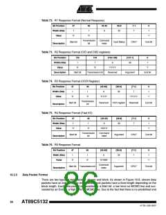
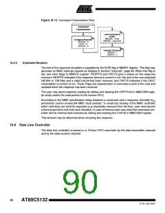
Figure 16-13. Command Transmission Flow
Command
Transmission
Load Command in
Buffer
MMCMD = Index
MMCMD = Argument
Configure Response
RESPEN = X
RFMT = X
CRCDIS = X
Transmit Command
CMDEN = 1
CMDEN = 0
16.5.2
Command Receiver
The end of the response reception is signalled by the EORI flag in MMINT register. This flag may
generate an MMC interrupt request as detailed in Section "Interrupt", page 96. When this flag is
set, two other flags in MMSTA register: RESPFS and CRC7S give a status on the response
received. RESPFS indicates if the response format is correct or not: the size is the one expected
(48 Bits or 136 Bits) and a valid End bit has been received, and CRC7S indicates if the CRC7
computation is correct or not. These Flags are cleared when a command is sent to the card and
updated when the response has been received.
The user may abort response reading by setting and clearing the CRPTR bit in MMCON0 regis-
ter which resets the read pointer to the receive FIFO.
According to the MMC specification delay between a command and a response (formally NCR
parameter) cannot exceed 64 MMC clock periods. To avoid any locking of the MMC controller
when card does not send its response (e.g. physically removed from the bus), user must launch
a timeout period to exit from such situation. In case of timeout user may reset the command con-
troller and its internal state machine by setting and clearing the CCR bit in MMCON2 register.
This timeout may be disarmed when receiving the response.
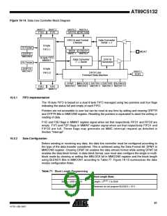
16.6 Data Line Controller
The data line controller is based on a 16-byte FIFO used both by the data transmitter channel
and by the data receiver channel.
90
AT89C5132
4173E–USB–09/07

 ATMEL [ ATMEL ]