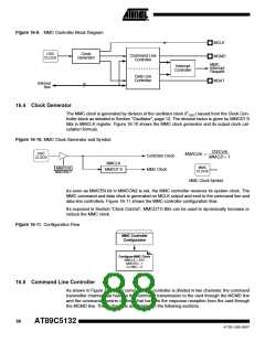
Figure 16-9. MMC Controller Block Diagram
MCLK
OSC
CLOCK
Clock
Generator
Command Line
Controller
MCMD
MMC
Interrupt
Request
Interrupt
Controller
Data Line
Controller
MDAT
Internal
Bus
8
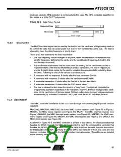
16.4 Clock Generator
The MMC clock is generated by division of the oscillator clock (FOSC) issued from the Clock Con-
troller block as detailed in Section "Oscillator", page 12. The division factor is given by MMCD7:0
Bits in MMCLK register. Figure 16-10 shows the MMC clock generator and its output clock cal-
culation formula.
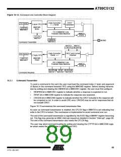
Figure 16-10. MMC Clock Generator and Symbol
OSCclk
MMCD + 1
OSC
CLOCK
MMCclk = -----------------------------
Controller Clock
MMC Clock
MMCLK
MMC
CLOCK
MMCEN
MMCON2.7
MMCD7:0
MMC Clock Symbol
As soon as MMCEN bit in MMCON2 is set, the MMC controller receives its system clock. The
MMC command and data clock is generated on MCLK output and sent to the command line and
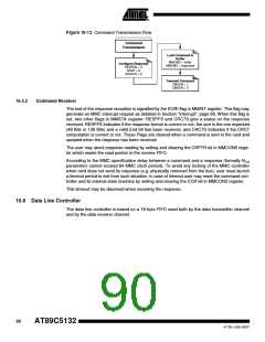
data line controllers. Figure 16-11 shows the MMC controller configuration flow.
As exposed in Section “Clock Control”, MMCD7:0 Bits can be used to dynamically increase or
reduce the MMC clock.
Figure 16-11. Configuration Flow
MMC Controller
Configuration
Configure MMC Clock
MMCLK = XXh
MMCEN = 1
FLOWC = 0
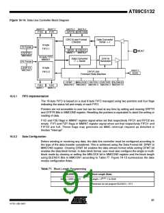
16.5 Command Line Controller
As shown in Figure 16-12, the command line controller is divided in two channels: the command
transmitter channel that handles the command transmission to the card through the MCMD line
and the command receiver channel that handles the response reception from the card through
the MCMD line. These channels are detailed in the following sections.
88
AT89C5132
4173E–USB–09/07

 ATMEL [ ATMEL ]