AT89C5132
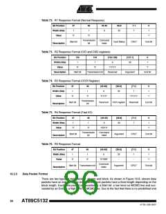
in stream packets, CRC protection is not included in this case. The CRC protection algorithm for
block data is a 16-bit CCITT polynomial.
Figure 16-8. Data Token Format
Sequential Data
Block Data
0
0
Content
1
1
Content
CRC
Block Length
16.2.6
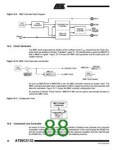
Clock Control
The MMC bus clock signal can be used by the host to turn the cards into energy saving mode or
to control the data flow (to avoid under-run or over-run conditions) on the bus. The host is
allowed to lower the clock frequency or shut it down.
There are a few restrictions the host must follow:
•
The bus frequency can be changed at any time (under the restrictions of maximum data
transfer frequency, defined by the cards, and the identification frequency defined by the
specification document).
•
It is an obvious requirement that the clock must be running for the card to output data or
response tokens. After the last MultiMedia Card bus transaction, the host is required, to
provide 8 (eight) clock cycles for the card to complete the operation before shutting down
the clock. Following is a list of the various bus transactions:
•
•
•
•
•
A command with no response. 8 clocks after the host command End bit.
A command with response. 8 clocks after the card command End bit.
A read data transaction. 8 clocks after the End bit of the last data block.
A write data transaction. 8 clocks after the CRC status token.
The host is allowed to shut down the clock of a “busy” card. The card will complete the
programming operation regardless of the host clock. However, the host must provide a clock
edge for the card to turn off its busy signal. Without a clock edge the card (unless previously
disconnected by a deselect command-CMD7) will force the MDAT line down, forever.
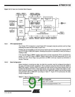
16.3 Description
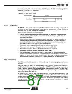
The MMC controller interfaces to the C51 core through the following eight special function
registers:
MMCON0, MMCON1, MMCON2, the three MMC control registers (see Figure 78 to Figure );
MMSTA, the MMC status register (see Figure 81); MMINT, the MMC interrupt register (see
Figure ); MMMSK, the MMC interrupt mask register (see Figure 83); MMCMD, the MMC com-
mand register (see Figure 84); MMDAT, the MMC data register (see Figure ); and MMCLK, the
MMC clock register (see Figure 86).
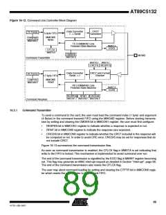
As shown in Figure 16-9, the MMC controller is divided in four blocks: the clock generator that
handles the MCLK (formally the MMC CLK) output to the card, the command line controller that
handles the MCMD (formally the MMC CMD) line traffic to or from the card, the data line control-
ler that handles the MDAT (formally the MMC DAT) line traffic to or from the card, and the
interrupt controller that handles the MMC controller interrupt sources. These blocks are detailed
in the following sections.
87
4173E–USB–09/07

 ATMEL [ ATMEL ]