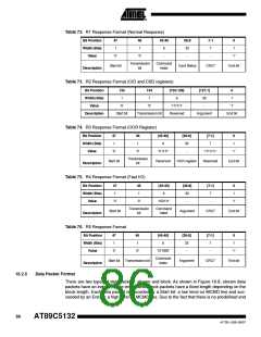
Table 72. R1 Response Format (Normal Response)
Bit Position
Width (Bits)
Value
47
1
46
1
45:40
39:8
32
-
7:1
7
0
1
6
-
‘0’
‘0’
-
‘1’
Transmission
bit
Command
Index
Start bit
Card Status
CRC7
End bit
Description
Table 73. R2 Response Format (CID and CSD registers)
Bit Position
Width (Bits)
Value
135
1
134
[133:128]
[127:1]
0
1
1
‘0’
6
32
‘0’
‘111111’
Reserved
-
‘1’
Description
Start bit
Transmission bit
Argument
End bit
Table 74. R3 Response Format (OCR Register)
Bit Position
Width (Bits)
Value
47
1
46
1
[45:40]
6
[39:8]
[7:1]
0
1
32
-
7
‘0’
‘0’
‘111111’
‘1111111’
‘1’
Transmission
bit
Start bit
Reserved
OCR register
Reserved
End bit
Description
Table 75. R4 Response Format (Fast I/O)
Bit Position
Width (Bits)
Value
47
1
46
1
[45:40]
6
[39:8]
[7:1]
0
1
32
-
7
-
‘0’
‘0’
‘100111’
‘1’
Transmission
bit
Command
Index
Start bit
Argument
CRC7
End bit
Description
Table 76. R5 Response Format
Bit Position
Width (Bits)
Value
47
1
46
1
[45:40]
6
[39:8]
[7:1]
0
1
32
-
7
-
‘0’
‘0’
‘101000’
‘1’
Command
Index
Start bit
Transmission bit
Argument
CRC7
End bit
Description
16.2.5
Data Packet Format
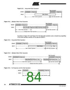
There are two types of data packets: stream and block. As shown in Figure 16-8, stream data
packets have an indeterminate length while block packets have a fixed length depending on the
block length. Each data packet is preceded by a Start bit: a low level on MCMD line and suc-
ceeded by an End bit: a high level on MCMD line. Due to the fact that there is no predefined end
86
AT89C5132
4173E–USB–09/07

 ATMEL [ ATMEL ]