AT85C51SND3Bx
–
the MSTR bit in SPCON is cleared
Clearing the MODF bit is accomplished by reading SPSCR with MODF bit set, followed
by a write to SPCON. SPI controller may be re-enabled (SPEN = 1) after the MODF bit
is cleared.
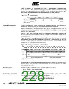
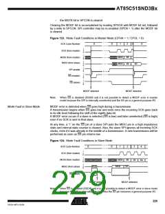
Figure 123. Mode Fault Conditions in Master Mode (CPHA = 1 / CPOL = 0)
SCK Cycle Number
SCK (from master)
0
0
1
2
3
0
1
z
0
1
z
0
MSB
MSB
B6
B6
MOSI (from master)
MISO (from slave)
1
z
0
B5
1
z
0
SPI enable
SS (master)
1
z
0
1
z
0
SS (slave)
MODF detected
MODF detected
Note:
When SS is disabled (SSDIS set) it is not possible to detect a MODF error in master
mode because the SPI is internally unselected and the SS pin is a general purpose I/O.
Mode Fault in Slave Mode
MODF error is detected when SS goes high during a transmission.
A transmission begins when SS goes low and ends once the incoming SCK goes back
to its idle level following the shift of the eighth data bit.
A MODF error occurs if a slave is selected (SS is low) and later unselected (SS is high)
even if no SCK is sent to that slave.
At any time, a ‘1’ on the SS pin of a slave SPI puts the MISO pin in a high impedance
state and internal state counter is cleared. Also, the slave SPI ignores all incoming SCK
clocks, even if it was already in the middle of a transmission. A new transmission will be
performed as soon as SS pin returns low.
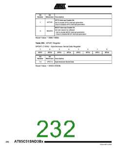
Figure 124. Mode Fault Conditions in Slave Mode
SCK Cycle Number
SCK (from master)
MOSI (from master)
MISO (from slave)
0
0
1
2
3
4
1
z
0
1
z
0
MSB
B6
B5
B4
1
z
0
MSB
B6
MSB
1
z
0
SS (slave)
MODF detected
MODF detected
Note:
when SS is disabled (SSDIS set) it is not possible to detect a MODF error in slave mode
because the SPI is internally selected. Also the SS pin becomes a general purpose I/O.
229
7632A–MP3–03/06

 ATMEL [ ATMEL ]