AT85C51SND3Bx
MMC/SD Controller
The AT85C51SND3Bx embed a MMC/SD controller allowing connecting of MMC and
SD cards in 1-bit or 4-bit modes. For MMC, 4-bit mode rely on the MMC Specification
V4.0.
The MMC/SD controller interfaces to the C51 core through the following special function
registers:
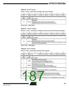
MMCON0, MMCON1, MMCON2, the three MMC control registers (see Table 221 to
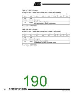
Table 223); MMBLP, the MMC Block Length register (see Table 224); MMSTA, the
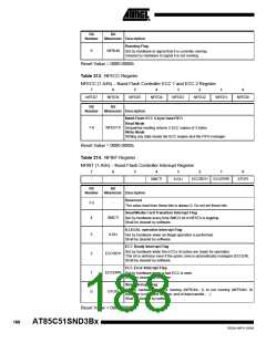
MMC status register (see Table 225); MMINT, the MMC interrupt register (see
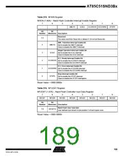
Table 226); MMMSK, the MMC interrupt mask register (see Table 227); MMCMD, the
MMC command register (see Table 228); and MMDAT, the MMC data register (see
Table 229).
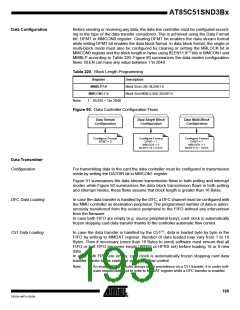
As shown in Figure 85, the MMC controller is based on four functional blocks: the clock
generator that handles the SDCLK (formally the MMC/SD CLK) output to the card, the
command line controller that handles the SDCMD (formally the MMC/SD CMD) line traf-
fic to or from the card, the data line controller that handles the SDDAT (formally the
MMC/SD DAT) line traffic to or from the card, and the interrupt controller that handles
the MMC controller interrupt sources. These blocks are detailed in the following
sections.
Figure 86 shows the external components to add for connecting a MMC or a SD card to
the AT85C51SND3B. SDDAT0 and SDCMD signals are connected to pull-up resistors.
Value of these resistors is detailed in the Section “DC Characteristics”, page 241.
Figure 85. MMC Controller Block Diagram
SDCLK
MMC
CLOCK
Command Line
Controller
SDCMD
MMC
Interrupt
Request
Interrupt
Controller
MMCEN
MMCON2.0
CPU
Bus
Data Line
Controller
SDDAT3:0
DFC
Bus
Figure 86. MMC Connection
RDAT
SDDAT0
SDCMD
IOVDD
RCMD
Clock Generator
The MMC clock is generated based on the clock generator as detailed in Section "MMC
Clock Generator", page 31. As soon as MMCEN bit in MMCON2 is set, the MMC con-
troller receives its system clock. The MMC command and data clock is generated on
SDCLK output and sent to the command line and data line controllers.
Command Line
Controller
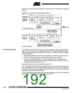
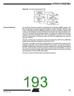
As shown in Figure 87, the command line controller is divided in 2 channels: the com-
mand transmitter channel that handles the command transmission to the card through
the SDCMD line and the command receiver channel that handles the response recep-
191
7632A–MP3–03/06

 ATMEL [ ATMEL ]