Data Line Controller
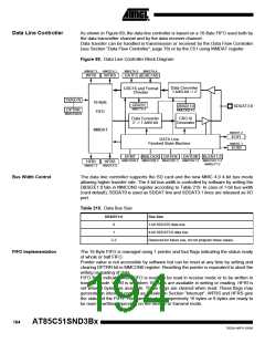
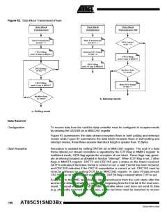
As shown in Figure 89, the data line controller is based on a 16-Byte FIFO used both by
the data transmitter channel and by the data receiver channel.
Data transfer can be handled in transmission or received by the Data Flow Controller
(see Section “Data Flow Controller”, page 78) or by the C51 using MMDAT register.
Figure 89. Data Line Controller Block Diagram
MMINT.3
MMSTA.1
MMSTA.3
MMSTA.4
WFRI
WFRS
DATFS CRC16S
Data Converter
1-bit/4-bit -> //
CRC16 and Format
Checker
TX/RX Ptr
16-Byte
CBUSY
MMSTA.5
DBSIZE1:0
MMCON2.4:3
SDDAT3:0
DPTRR
MMCON0.6
FIFO
Data Converter
// -> 1-bit/4-bit
CRC16
Generator
MMDAT
MMINT.4
EOFI
DATA Line
Finished State Machine
MMINT.1
EOBI
DFMT
MBLOCK DATEN
DATDIR BLEN11:0
MMCON0.2 MMCON0.3 MMCON1.2 MMCON1.3 MMCON1.7:4
MMBLP7:0
HFRI
MMINT.2
HFRS
MMSTA.0
Bus Width Control
The data line controller supports the SD card and the new MMC 4.0 4-bit bus mode
allowing higher transfer rate. The 4-bit bus width is controlled by software by setting the
DBSIZE1:0 bits in MMCON2 register according to Table 219. In case of 1-bit bus width
(card default), SDDAT0 is used as SDDAT line and SDDAT3:1 lines are released as I/O
port.
Table 219. Data Bus Size
DBSIZE1:0
Bus Size
0
1
1-bit SDDAT0 data bus.
4-bit SDDAT3:0 data bus.
2-3
Reserved for future use, do not program these values.
FIFO Implementation
The 16-Byte FIFO is managed using 1 pointer and four flags indicating the status ready
of whole or half FIFO.
Pointer value is not accessible by software but can be reset at any time by setting and
clearing DPTRR bit in MMCON0 register. Resetting the pointer is equivalent to abort the
writing or reading of data.
FIFO flags indicate when FIFO is ready to be read in receive mode or to be written in
transmit mode. WFRI is set when 16 bytes are available in writing or reading. HFRI is
set when 8 bytes are available. These flags are cleared when read. These flags may
generate an interrupt request as detailed in Section “Interrupt”. WFRS and HFRS give
the status of the FIFO. They are set when respectively 16 bytes or 8 bytes are ready to
be read or written depending on the receive or transmit mode.
194
AT85C51SND3Bx
7632A–MP3–03/06

 ATMEL [ ATMEL ]