AT85C51SND3Bx
Data Configuration
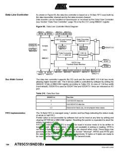
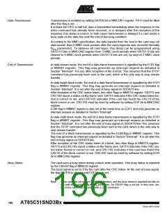
Before sending or receiving any data, the data line controller must be configured accord-
ing to the type of the data transfer considered. This is achieved using the Data Format
bit: DFMT in MMCON0 register. Clearing DFMT bit enables the data stream format
while setting DFMT bit enables the data block format. In data block format, the single or
multi-block mode must also be configured by clearing or setting the MBLOCK bit in
MMCON0 register and the block length in bytes using BLEN11:0(1) bits in MMCON1 and
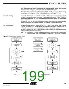
MMBLP according to Table 220. Figure 90 summarizes the data modes configuration
flows. BLEN can have any value between 1 to 2048.
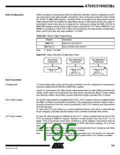
Table 220. Block Length Programming
Register
Description
MMBLP7:0
Block Size LSB: BLEN11:8
Block Size MSB (LSN): BLEN7:0
MMCON1.7:4
1. BLEN = 1to 2048
Note:
Figure 90. Data Controller Configuration Flows
Data Stream
Configuration
Data Single Block
Configuration
Data Multi-Block
Configuration
Configure Format
Configure Format
DFMT = 1
Configure Format
DFMT = 1
DFMT = 0
MBLOCK = 0
MBLOCK = 1
BLEN11:0 = XXXh
BLEN11:0 = XXXh
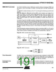
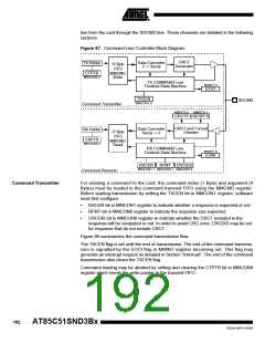
Data Transmitter
Configuration
For transmitting data to the card the data controller must be configured in transmission
mode by setting the DATDIR bit in MMCON1 register.
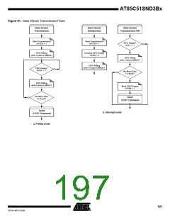
Figure 91 summarizes the data stream transmission flows in both polling and interrupt
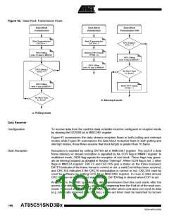
modes while Figure 92 summarizes the data block transmission flows in both polling
and interrupt modes, these flows assume that block length is greater than 16 Bytes.
DFC Data Loading
C51 Data Loading
In case the data transfer is handled by the DFC, a DFC channel must be configured with
the MMC controller as destination peripheral. The programmed number of data is auton-
omously transferred from the source peripheral to the FIFO without any intervention
from the firmware.
In case both FIFO are empty (e.g. source peripheral busy), card clock is automatically
frozen stopping card data transfer thanks to the controller automatic flow control.
In case the data transfer is handled by the C51(1), data is loaded byte by byte in the
FIFO by writing to MMDAT register. Number of data loaded may vary from 1 to 16
Bytes. Then if necessary (more than 16 Bytes to send) software must ensure that all
FIFO or half FIFO becomes empty (WFRS or HFRS set) before loading 16 or 8 new
data.
In case both FIFO are empty, card clock is automatically frozen stopping card data
transfer thanks to the controller automatic flow control.
Note:
1. An enabled DFC transfer always takes precedence on a C51 transfer, it is under soft-
ware responsibility not to write to MMDAT register while a DFC transfer is enabled.
195
7632A–MP3–03/06

 ATMEL [ ATMEL ]