AT8xC51SND2C
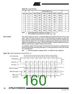
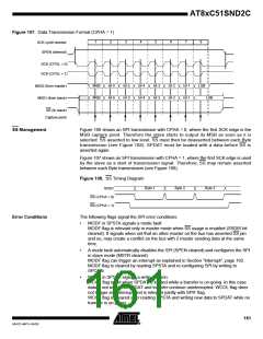
Figure 107. Data Transmission Format (CPHA = 1)
1
2
3
4
5
6
7
8
SCK cycle number
SPEN (internal)
SCK (CPOL = 0)
SCK (CPOL = 1)
MSB
MSB
bit 6
bit 6
bit 5
bit 5
bit 4
bit 4
bit 3
bit 3
bit 2
bit 2
bit 1
bit 1
LSB
LSB
MOSI (from master)
MISO (from slave)
SS (to slave)
Capture point
SS Management
Figure 106 shows an SPI transmission with CPHA = 0, where the first SCK edge is the
MSB capture point. Therefore the slave starts to output its MSB as soon as it is
selected: SS asserted to low level. SS must then be deasserted between each Byte
transmission (see Figure 108). SPDAT must be loaded with a data before SS is
asserted again.
Figure 107 shows an SPI transmission with CPHA = 1, where the first SCK edge is used
by the slave as a start of transmission signal. Therefore, SS may remain asserted
between each Byte transmission (see Figure 108).
Figure 108. SS Timing Diagram
Byte 1
Byte 2
Byte 3
SI/SO
SS (CPHA = 0)
SS (CPHA = 1)
Error Conditions
The following flags signal the SPI error conditions:
•
•
•
MODF in SPSTA signals a mode fault.
MODF flag is relevant only in master mode when SS usage is enabled (SSDIS bit
cleared). It signals when set that an other master on the bus has asserted SS pin
and so, may create a conflict on the bus with 2 master sending data at the same
time.
A mode fault automatically disables the SPI (SPEN cleared) and configures the SPI
in slave mode (MSTR cleared).
MODF flag can trigger an interrupt as explained in Section "Interrupt", page 162.
MODF flag is cleared by reading SPSTA and re-configuring SPI by writing to
SPCON.
WCOL in SPSTA signals a write collision.
WCOL flag is set when SPDAT is loaded while a transfer is on-going. In this case
data is not written to SPDAT and transfer continue uninterrupted. WCOL flag does
not trigger any interrupt and is relevant jointly with SPIF flag.
WCOL flag is cleared after reading SPSTA and writing new data to SPDAT while no
transfer is on-going.
161
4341D–MP3–04/05

 ATMEL [ ATMEL ]