AT7908E
Operations 5 and 6
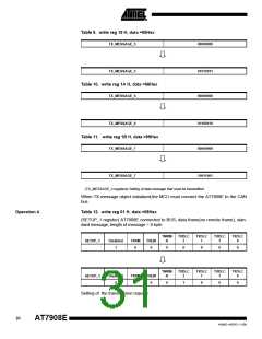
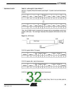
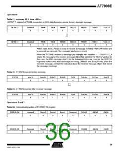
Table 13. write reg 03 H, data =0Ahex (1)
(SETUP_3 register) Resynchronisation jump length = 2 system clock and transmission
request.
Abort
SETUP_3
RxClr
0
Reset
0
IntClr
0
Tx
Txreq
0
RSJ2
0
RSJ1
1
RSJ0
0
0
Abort
Tx
SETUP_3
RxClr
0
Reset
0
IntClr
0
Txreq
0
RSJ2
0
RSJ1
1
RSJ0
0
0
Then, the AT7908E starts to transmit the message until an acknowledge comes from
another CAN node. The next figure illustrates the standard CAN format on the CAN
BUS:
Figure 12. DATA frame
SOF
ACK
Data Frame
End of
Frame
INT
Generation
STATUS register before TX request:
Sync
Rx
Rxbuf
1
Rxbuf
0
TxActiv
ErrPas
STATUS
SyncTx
0
TxOK
0
e
s
BusOff
0
0
0
0
0
0
STATUS register after start of transmission:
Sync
Rx
Rxbuf
1
Rxbuf
0
TxActiv
e
ErrPas
s
STATUS
SyncTx
0
TxOK
0
BusOff
0
0
0
0
1
0
STATUS register after completion of correct transmission:
1.
The five Gray bit are not updated after setting (Txreq). These bit are not written inside the
registers.
32
4268D–AERO–11/09

 ATMEL [ ATMEL ]