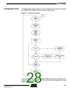
Initialization and Transmission of the Data Frame with the INT Generation and Behavior of the
MCU After the Interrupt is Received
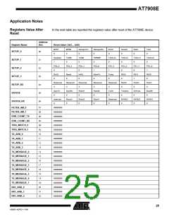
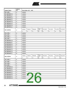
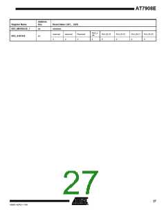
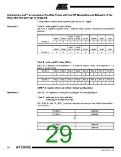
Configuration of all the setup registers after the RESET signal.
Operation 1
Table 1. write reg 00 H, data =01Hex
(SETUP_0 register) system clock = external clock, enable transmission completed
interrupt
Gens
Gens
BPR1
0
BPR0
0
yncTx
yncRx
Errint
0
Overint
0
Rxint
0
Txint
0
SETUP_0
SETUP_0
0
0
Gens
yncTx
Gens
yncRx
BPR1
0
BPR0
0
Errint
0
Overint
0
Rxint
0
Txint
1
0
0
Table 2. write reg 02 H, data =69Hex
(SETUP_2 register) Time segment 2 = 6 pulse of system clock; Time segment 1 = 8
pulse of system clock.
SETUP_2
PS2_3
PS2_2
PS2_1
PS2_0
PS1_3
PS1_2
PS1_1
PS1_0
0
1
0
1
1
0
0
1
SETUP_2
PS2_3
0
PS2_2
1
PS2_1
1
PS2_0
0
PS1_3
1
PS1_2
0
PS1_1
0
PS1_0
1
SETUP_3 register will be not written ( default configuration)
Operation 2
After SETUP registers is necessary to configure TX message object:
Table 3. write reg 10 H, data =AA Hex
write reg 11 H, data =AA Hex
(TX_ARB_0= and TX_ARB_1 registers) identifier of message that will be transmitted =
10101010101
TX_ARB_0
TX_ARB_1
00000000
00000000
TX_ARB_0
TX_ARB_1
10101010
10101010
29
AT7908E
4268D–AERO–11/09

 ATMEL [ ATMEL ]