AT7908E
Configuration Flow
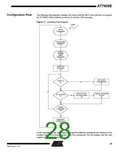
The following flow diagram explains the action that the MCU must perform to program
the AT7908E CAN controller to send or to receive CAN message.
Figure 11. Operating Flow Diagram
reset
Device
Configuration
(1)
Transmit buffer
Initialisation
(2)
Receiver
message
object
configuration
(3)
Enable BUS
Connection
(4)
SET START
TRANSMISSION
(6)
START TX
yes
(5)
NO
NO
READ STATUS
(& receiver buffer)
(8)
Clear INT and receiver
INT by CASA2
(7)
Yes
STATUS
(9)
NO
Change
Configuration
(10)
Yes
Disable BUS
CONNECTION
(11)
In the examples of the followings paragraph the different operations are referred to the
number reported on flow diagram. After the commands, the old register and the new
register values are reported.
28
4268D–AERO–11/09

 ATMEL [ ATMEL ]