AT7908E
Operation4
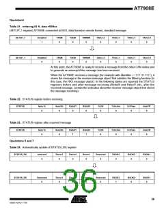
Table 21. write reg 01 H, data =00Hex
(SETUP_1 register) AT7908E connected to BUS, data frame(no remote frame), standard message
SETUP_1
Disabled
1
TXRM
0
TXEM
0
TMRMR
0
TXDLC3
0
TXDLC1
0
TXDLC1
TXDLC0
0
0
SETUP_1
Disabled
0
TXRM
0
TXEM
0
TMRMR
0
TXDLC3
0
TXDLC1
0
TXDLC1
0
TXDLC0
0
At this point, the AT7908E is ready to receive a message from the other CAN nodes and
to generate an interrupt if the message has been received.
When the AT7908E receives a message (for example with Identifier = 11111111111), it
stores the message in the receiver message object that satisfies the filtering function (in
this case, the RX3 message object). In the following tables are reported the STATUS
registers before and after message receiving (Rxbuf0 and Rxbuf1 bits, after the
received message, contain the indication about the receiver message object that stored
the message incoming).
Table 22. STATUS register before receiving.
STATUS
SyncTx
0
SyncRx
0
Rxbuf1
0
Rxbuf0
0
TxOK
0
TxActive
0
ErrPass
0
BusOff
0
Table 23. STATUS register after received message
STATUS
SyncTx
0
SyncRx
0
Rxbuf1
1
Rxbuf0
1
TxOK
0
TxActive
0
ErrPass
0
BusOff
0
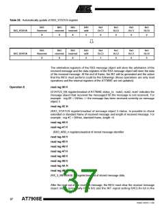
Operations 5 and 7
Table 24. Automatically update of STATUS_RX register
STATUS_RX
reserved
0
Rxovr3
0
Rxovr2
0
Rxovr1
0
Reserved
0
RXOK3
0
RXOK2
0
RXOK1
0
STATUS_RX
Reserved
0
Rxovr3
0
Rxovr2
0
Rxovr1
0
Reserved
0
RXOK3
1
RXOK2
0
RXOK1
0
36
4268D–AERO–11/09

 ATMEL [ ATMEL ]