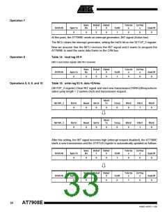
Operation 7
Sync
Rx
Rxbuf
1
Rxbuf
0
TxActiv
e
ErrPas
s
STATUS
SyncTx
0
TxOK
1
BusOff
0
0
0
0
0
0
At this point, the AT7908E sends an interrupt generation ;INT signal (Active low).
The MCU clears the interrupt generation, setting the IntClr bit on the SETUP_3 register.
Now we assume that the MCU receives the INT signal and it wants to program the
AT7908E to send the same data frame on the CAN bus.
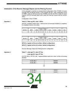
Operation 8
Table 14. read reg 05 H
(MCU read status register after INT received)
Sync
Rx
Rxbuf
1
Rxbuf
0
TxActiv
e
ErrPas
s
STATUS
SyncTx
0
TxOK
1
BusOff
0
0
0
0
0
0
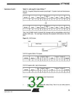
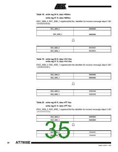
Operations 5, 6, 9, and 10
Table 15. write reg 03 H, data =2AHex
(SETUP_3 register) Clear INT signal and start new transmission(TXREQ)Resynchroni-
sation jump length = 2 system clock and transmission request.
Abort
SETUP_3
SETUP_3
RxClr
0
Reset
0
IntClr
0
Tx
Txreq
0
RSJ2
0
RSJ1
1
RSJ0
0
0
Abort
Tx
RxClr
0
Reset
0
IntClr
0
Txreq
0
RSJ2
0
RSJ1
1
RSJ0
0
0
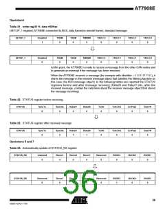
After this setting, the INT signal becomes high (interrupt request disabled), the AT7908E
starts a new transmission and the STATUS register is automatically updated as follows:
Sync
Rx
Rxbuf
1
Rxbuf
0
TxActiv
e
ErrPas
s
STATUS
SyncTx
0
TxOK
1
BusOff
0
0
0
0
0
0
Sync
Rx
Rxbuf
1
Rxbuf
0
TxActiv
e
ErrPas
s
STATUS
SyncTx
0
TxOK
0
BusOff
0
0
0
0
1
0
33
AT7908E
4268D–AERO–11/09

 ATMEL [ ATMEL ]