AS5050
Datasheet - Detailed Description
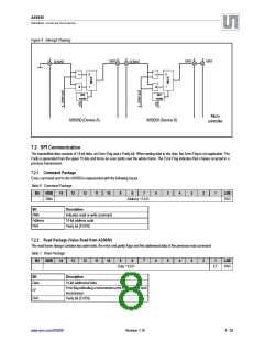
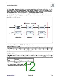
Figure 4. Interrupt Chaining
XINT
XINT
XINT
XENINT
XENINT
=1
&
=1
&
0
1
0
1
INT
mode
INT
mode
Micro
controller
AS5050 (Device A)
AS5050 (Device B)
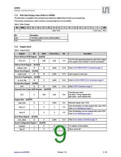
7.2 SPI Communication
The transmitted data consists of 14-bit data, an Error-Flag and a Parity bit. When writing data to the chip, the Error-Flag is not applicable. The
Parity is generated from the upper 15 bits and forms an even parity over the whole frame. The Error-Flag indicates that a failure occurred in a
previous transmission.
7.2.1 Command Package
Every command sent to the AS5050 is represented with the following layout.
Table 6. Command Package
Bit
MSB
14
13
12
11
10
9
8
7
6
5
4
3
2
1
LSB
RWn
Address <13:0>
PAR
Bit
Description
RWn
Indicates read or write command
14-bit address code
Address
PAR
Parity bit (EVEN)
7.2.2 Read Package (Value Read from AS5050)
The read frame always contains two alarm bits, the error and parity flags and the addressed data of the previous read command.
Table 7. Read Package
Bit
MSB
14
13
12
11
10
9
8
7
6
5
4
3
2
1
LSB
Data <13:0>
EF
PAR
Bit
Description
14-bit addressed data
Data
Error flag indicating a transmission error in a previous host
transmission
EF
PAR
Parity bit (EVEN)
www.ams.com/AS5050
Revision 1.16
8 - 25

 AMSCO [ AMS(艾迈斯) ]