AS5050
Datasheet - Detailed Description
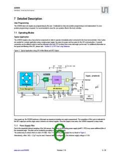
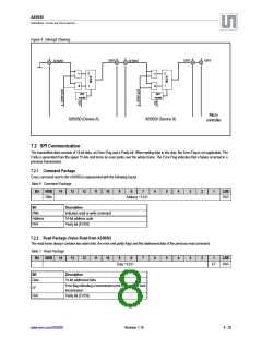
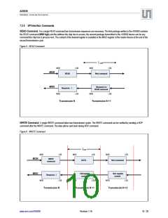
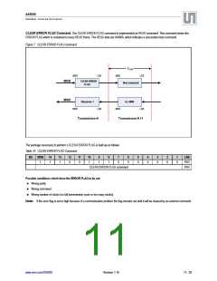
7.1.2 Reading an Angle
The external microcontroller can respond to the INT request by reading the angle value from the AS5050 over the SPI interface. Once the angle
value is read, the INT output is cleared again.
Sending a “read angle” command by the SPI interface also automatically powers up the chip and starts another angle measurement. As soon as
the microcontroller has completed reading of the angle value, the INT output is cleared and a new result is stored in the angle register. The
completion of the angle measurement is again indicated by setting the INT output and a corresponding flag in the status register.
Reducing the Angle Jitter. Due to the measurement principle of the chip, only a single angle measurement is performed in very short time
after each power-up sequence. As soon as the measurement of one angle is completed, the chip suspends to power-down state. An on-chip
filtering of the angle value by digital averaging is not implemented, as this would require more than one angle measurement and consequently, a
longer power- up time which is not desired in low-power applications.
The angle jitter can be reduced by averaging of several angle samples in the external microcontroller. For example, an averaging of 4 samples
reduces the noise related jitter by 6dB (50%).
7.1.3 Low Power Mode
After completing the readout of an angle value, the device is in very low power condition. The AS5050 remains in sleep mode until it receives
another angle reading request over the SPI interface. The average power consumption therefore depends on the interval, at which the external
controller reads an angle over the SPI Interface. The timing ratio between active and sleep phase:
(EQ 1)
ton ∗ Ion + toff ∗ Ioff
Iavg
=
ton + toff
Where:
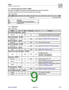
ton = Minimum on-time for power-up and angle measurement
toff = Pause interval between measurements, determined by the polling rate of the external microcontroller
on = Current consumption in active mode
430µs
I
8.5mA (maximum)
3µA
Ioff = Current consumption in sleep mode
Examples:
3000 measurements per second (continuous mode)
1000 measurements per second
100 measurements per second
10 measurements per second
I = 8.5mA
Iavg = 3.7mA
Iavg = 370µA
Iavg = 40µA
Note: Even in low power mode, the power supply must be capable of supporting the active current at least for the time Ton, until the AS5055
is suspended to sleep mode.
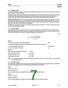
7.1.4 Interrupt Chaining
Every chip contains a configurable gate to combine its own internally generated interrupt signal with a signal applied externally over the XENINT-
pin. The INT-mode register is preset via an OTP register and can be overwritten by the SPI interface.
Case A.
Device A is set to mode 0
Device B is set to mode 0
The micro controller recognizes an interrupt if both devices signalize that the computation is finished.
Case B.
Device A is set to mode 0
Device B is set to mode 1
The micro controller recognizes an interrupt if one of the two devices signalize that the computation is finished.
www.ams.com/AS5050
Revision 1.16
7 - 25

 AMSCO [ AMS(艾迈斯) ]