AS5050
Datasheet - Detailed Description
7 Detailed Description
User Programming.
The AS5050 does not require any programming by the user. A dedicated on-chip zero position programming is not implemented. If a zero
position programming is required, it is recommended to store the zero position offset in the host controller.
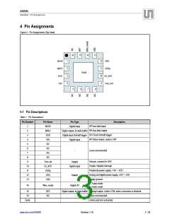
7.1 Operating Modes
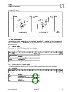
Typical Application.
The AS5050 requires only a few external components in order to operate immediately when connected to the host microcontroller. Only 6 wires
are needed for a simple application using a single power supply: two wires for power and four wires for the SPI communication. A seventh
connection can be added in order to send an interrupt to the host CPU to inform that a new valid angle can be read. For additional information on
the layout and filtering of the SPI, please refer Section 8.1.4 SPI Over Long Distances
.
Figure 3. Typical Application Using SPI 4-Wire Mode and INT/ Output
15 ohm
VDD
4µ7
DC 3.0V ~ 3.6V
VDD
AS5050
Supply: peripherals
Interrupt
INT/
ADC
Cordic
EN_INT/
Hall Sensors
µC
SPI Interface
VDDp
Power Management
VDDp
100n
SS/
VSS
Test_coil
Wire
mode
SPI
Interface
VDDp
Upon power-up, the AS5050 performs a full power-up sequence including one angle measurement. The completion of this cycle is indicated at
the INT/ output pin and the angle value is stored in an internal register. Once this output is low active, the AS5050 suspends to sleep mode.
7.1.1 Power Supply Filter
Due to the sequential internal sampling of the Hall sensors, fluctuations on the analog power supply (pin#12: VDD) may cause additional jitter of
the measured angle. This jitter can be avoided by providing a stable VDD supply.
The easiest way to achieve that is to add a RC filter: 15Ω + 4.7µF in the power supply line as shown in Figure 3.
Alternatively, a filter: 33Ω + 2.2µF may be used. However with this configuration, the minimum supply voltage is 3.15V.
www.ams.com/AS5050
Revision 1.16
6 - 25

 AMSCO [ AMS(艾迈斯) ]