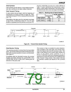
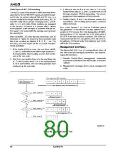
3. If bit A is a zero, bit B is a zero, and bit C is a one,
the next three bits (D, E, and F) select which one of
the eight positions 17-24 is transmitted. The encod-
ing process then continues at the root node.
Data Symbol RLL25 Encoding
The RLL25 code is the version of TM32 that was devel-
oped for the HomePNA PHY. It produces both the high-
est bit rate for a given value of ISBI and TIC size. In a
manner similar to run length limited disk coding, RLL25
encodes data bits in groups of varying sizes, specifi-
cally: 3, 4, 5, and 6 bits. Pulse positions are assigned
to the encoded bit groups in a manner, which causes
more data bits to be encoded in positions that are far-
ther apart. This keeps both the average and minimum
bit rates higher.
4. Finally, if bits A, B, and C are all zeros, position 0 is
transmitted. The encoding process then continues
at the root node.
As a result, Symbol 0 encodes the 3-bit data pattern
000, positions 1-8 encode the 4-bit data pattern 1BCD,
positions 9-16 encode the 5-bit data pattern 01CDE,
and positions 17-24 encode the 6-bit data pattern
001DEF. If the data encoded is random, 50% of the po-
sitions used will be for 4-bit patterns, 25% will be for 5-
bit patterns, 12.5% will be for 6-bit patterns, and 12.5%
will be for 3-bit patterns.
Data symbol RLL25 codes data by traversing a tree as
illustrated in Figure 42. Assuming that successive data
bits to be encoded are labeled A, B, C, D,…, etc. The
encoding process begins at the root node and pro-
ceeds as follows:
Management Interfaces
1. If the first bit (bit A) is a one, the next three bits (B,
C, and D) select which one of the eight positions 1-
8 is transmitted. The encoding process then contin-
ues at the root node.
The HomePNA PHY may be managed from either of
two interfaces (the managed parameters vary depend-
ing on the interface):
1. Remote Control-Word management commands
embedded in the HomePNA AID header on the wire
network.
2. If bit A is a zero and bit B is a one, the next three bits
(C, D, and E) select which one of the eight positions
9-16 is transmitted. The encoding process then
continues at the root node.
2. Management messages from a local management
entity.
Data stream from MAC controller
Start: Examine the next
bits to be encoded
A
B
C
D
E
F
Encoded and
Awaiting coding and transmission
1
Send symbol 1-8
A = ?
1
B
C
D
0
These select position 1 - 8
1
Send symbol 9-16
Send symbol 17-24
Send symbol 0
B = ?
0
0
0
1
C
D
E
0
These select position 9 - 16
1
C = ?
0
1
D
E
F
0
These select position 17- 24
0
1
0
22206B-46
Figure 42. RLL 25 Coding Tree
80
Am79C978

 AMD [ AMD ]