formed first. INIT is not cleared
when the initialization sequence
has completed.
dress. Therefore, whenever
SSIZE32 = 0, the IADR[31:24]
bits will be appended to the 24-bit
initialization address, to each 24-
bit descriptor base address, and
to each beginning 24-bit buffer
address in order to form complete
32-bit addresses. The upper 8
bits that exist in the descriptor ad-
dress registers and the buffer ad-
dress registers which are stored
on board the Am79C978 control-
ler will be overwritten with the
IADR[31:24] value, so that CSR
accesses to these registers will
show the 32-bit address that in-
cludes the appended field.
This bit is always read/write ac-
cessible. INIT is set by writing a 1.
Writing a 0 has no effect. INIT is
cleared
by
H_RESET,
S_RESET, or by setting the
STOP bit.
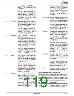
CSR1: Initialization Block Address 0
Bit
Name
Description
31-16 RES
Reserved locations. Written as
zeros and read as undefined.
15-0
IADR[15:0] Lower 16 bits of the address of
the Initialization Block. Bit loca-
tions 1 and 0 must both be 0 to
align the initialization block to a
DWord boundary.
If SSIZE32 = 1, then software will
provide 32-bit pointer values for
all of the shared software struc-
tures - i.e., descriptor bases and
buffer addresses, and therefore,
IADR[31:24] will not be written to
the upper 8 bits of any of these
resources, but it will be used as
the upper 8 bits of the initializa-
tion address.
This register is aliased with
CSR16.
These bits are read/write acces-
sible only when either the STOP
or the SPND bit is set. These bits
are unaffected by H_RESET,
S_RESET, or by setting the
STOP bit.
This register is aliased with
CSR17.
These bits are read/write acces-
sible only when either the STOP
or the SPND bit is set. These bits
are unaffected by H_RESET,
S_RESET, or by setting the
STOP bit.
CSR2: Initialization Block Address 1
Bit
Name
Description
31-16 RES
Reserved locations. Written as
zeros and read as undefined.
7-0
IADR[23:16] Bits 23 through 16 of the address
of the Initialization Block. When-
ever this register is written,
CSR17 is updated with CSR2’s
contents.
15-8
IADR[31:24] If SSIZE32 is set (BCR20, bit 8),
then the IADR[31:24] bits will be
used strictly as the upper 8 bits of
the initialization block address.
However, if SSIZE32 is reset
(BCR20, bit 8), then the
IADR[31:24] bits will be used to
generate the upper 8 bits of all
bus mastering addresses, as re-
quired for a 32-bit address bus.
Note that the 16-bit software
structures specified by the
SSIZE32 = 0 setting will yield
only 24 bits of address for the
Am79C978 bus master access-
es, while the 32-bit hardware for
which the Am79C978 controller is
intended will require 32 bits of ad-
These bits are read/write acces-
sible only when either the STOP
or the SPND bit is set. These bits
are unaffected by H_RESET,
S_RESET, or by setting the
STOP bit.
CSR3: Interrupt Masks and Deferral Control
Bit
Name
Description
Reserved locations. Written as
zeros and read as undefined.
31-16 RES
Am79C978
115

 AMD [ AMD ]