AMD
P R E L I M I N A R Y
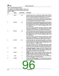
5
4
MOREINT
TXCNT
1
0
MORE Interrupts. MOREINT will become set whenever there are
interrupt bits set in Interrupt Register 3 (TCR11). Note that
MOREINT bit does not reflect the state of interrupt status bits from
Interrupt Register 2 (TIR5). There is an unmask bit for MOREINT,
and there are also individual unmask bits for the interrupts in Inter-
rupt Register 3 (TCR11).
TX Count reached. TXCNT becomes set to a 1 when the TX Byte
count limit of TIR14 and TIR15 has been reached as indicated by
the TIR12 and TIR13 counter. Note that reaching the byte count
limit will not cause TX operations to automatically cease. TX data
transmission ceases only when the TX FIFO has become empty.
3
2
TXDONE
CRCS
0
0
TXDONE. Indicates that the CRC has been sent for the current TX
frame. If the option for NO TX CRC has been selected, then
TXDONE will be set to a 1 when the last data bit for the frame has
been sent.
CRC Start. CRCS will be set to a 1 by the Am79C930 device when
the first bit of the CRC is being transmitted. If the NO TX CRC option
has been set, then CRCS will not become set.
1
0
SDSNT
TXFBN
0
1
Start of Frame Delimiter Sent during a TX operation.
TX FIFO Byte Needed. Indicates that the TX FIFO is not full.
TIR5: Interrupt Register
The TAI Interrupt Register 2 provides interrupt status in-
formation. Any interrupt bit may be cleared by writing a 1
to the bit location. Writing a 0 to a bit location has no ef-
fect on the bit value. When the unmask bit for any
interrupt is set to 0, then the bit in the Interrupt register
may still become set, but no interrupt to the 80188 em-
bedded controller will occur.
Bit
Name
Reset Value
Description
7
RXCNT
0
RX Count reached. RXCNT becomes set to a 1 when the RX Byte
count limit of TIR14 and TIR15 has been reached as indicated by
the TIR12 and TIR13 counter. Note that reaching the byte count
limit will not cause RX operations to automatically cease. RX
data reception ceases only when the RX FIFO is reset by the
80188 controller.
6
5
CRC8G
0
0
CRC8 Good. The CRC8 machine has detected a good CRC and
has latched the byte count that was active at the time that the CRC
was good.
CRC32G
CRC32 Good. The CRC32 machine has detected a good CRC and
has latched the byte count that was active at the time that the CRC
was good.
4
3
RXFOR
RXFBA
0
0
RX FIFO Overrun. The RX FIFO encountered an overrun condition.
RX FIFO Byte Available. The RX FIFO has at least one byte of data
available for removal. The status register for the RX FIFO indicates
the exact number of bytes in the RX FIFO.
2
1
0
SDF
BCF
1
0
0
Start Delimiter Found. The SFD has been found, indicating that the
receive state machine will now begin placing received bytes into the
RX FIFO.
Busy Channel Found. BCF is set to 1 by the Am79C930 device
when a busy channel has been found by the CCA logic. That is,
whenever CHBSY=1, which implies that the channel is busy.
ALOKI
Antenna Lock Interrupt. ALOKI becomes set when the antenna se-
lection logic has chosen an antenna based upon the programmed
antenna selection criteria.
92
Am79C930

 AMD [ AMD ]