AMD
P R E L I M I N A R Y
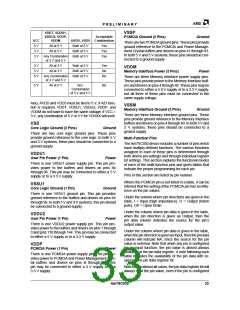
VDDT, VDDU1,
VDDU2, VDDP,
VDDM
VSSP
Acceptable
AVDD, VDD5 Combination
PCMCIA Ground (2 Pins)
Ground
VCC
5 V
There are two PCMCIA ground pins. These pins provide
ground reference to the PCMCIA and Power Manage-
ment Crystal buffers and drivers on pins 41 through 83.
In both 5 V and 3 V systems, these pins should be con-
nected to a ground supply.
All at 5 V
All at 5 V
Both at 5 V
Both at 5 V
Both at 5 V
Yes
Yes
Yes
3 V
3 V
Any Combination
of 3 V and 5 V
3 V
5 V
5 V
All at 3 V
All at 3 V
Both at 5 V
Both at 5 V
Both at 5 V
Yes
No
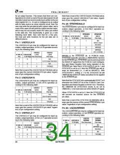
VDDM
Memory Interface Power (3 Pins)
Power
Any Combination
of 3 V and 5 V
No
There are three Memory Interface power supply pins.
These pins provide power to the Memory Interface buff-
ers and drivers on pins 4 through 40. These pins may be
connected to either a 5.0 V supply or to a 3.3 V supply,
but all three of these pins must be connected to the
same supply voltage.
5 V
All at 5 V
Any
Combination
of 3 V and 5 V
No
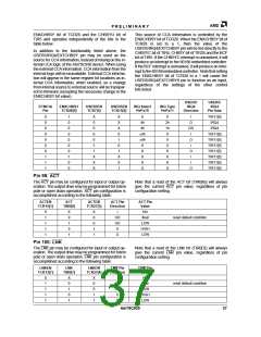
Also, AVDD and VDD5 must be tied to 5 V, if A/D func-
tion is required. VDDT, VDDU1, VDDU2, VDDP, and
VDDM do not have to have the same voltage. If VCC =
3 V, any combination of 5 V or 3 V for VDDXX will work.
VSSM
Memory Interface Ground (3 Pins)
Ground
There are three Memory Interface ground pins. These
pins provide ground reference to the Memory Interface
buffers and drivers on pins 4 through 40. In both 5 V and
3 V systems, these pins should be connected to a
ground supply.
VSS
Core Logic Ground (2 Pins)
Ground
There are two core logic ground pins. These pins
provide ground reference to the core logic. In both 5 V
and 3 V systems, these pins should be connected to a
ground supply.
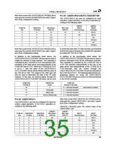
Multi-Function Pins
The Am79C930 device includes a number of pins which
have multiply-defined functions. The various functions
assigned to each of these pins is determined through
both device pin settings and through individual register
bit settings. This section explains the functional modes
of each of the multi-function pins and gives tables that
indicate the proper programming for each pin.
VDDU1
User Pin Power (1 Pin)
Power
There is one VDDU1 power supply pin. This pin pro-
vides power to the buffers and drivers on pins 84
through 96. This pin may be connected to either a 5 V
supply or to a 3.3 V supply.
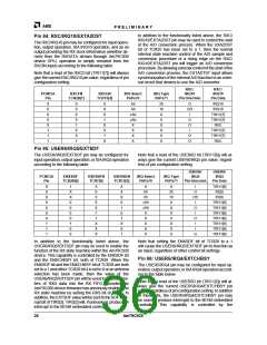
Pins in this section are listed by pin number.
Where the PCMCIA pin is not listed in a table, it can be
inferred that the setting of the PCMCIA pin has no influ-
ence on the pin values.
VSSU1
Core Logic Ground (1 Pin)
Ground
There is one VSSU1 ground pin. This pin provides
ground reference to the buffers and drivers on pins 84
through 96. In both 5 V and 3 V systems, this pin should
be connected to a ground supply.
Under the column where pin directions are given in the
table, I = Input (high impedance), O = Output (totem
pole), OD = Open Drain.
Under the column where pin data is given in the table,
when the pin direction is given as Output, then the
pin data column indicates the source for the pin’s
output value.
VDDU2
User Pin Power (1 Pin)
Power
There is one VDDU2 power supply pin. This pin pro-
vides power to the buffers and drivers on pins 1 through
3 and pins 139 through 144. This pin may be connected
to either a 5 V supply or to a 3.3 V supply.
Under the column where pin data is given in the table,
when the pin direction is given as Input, then the pin data
column will indicate NA, since the source for the pin
value is external. Note that when any pin is configured
for an input function, the pin value is almost always
available at the pin data register. A note following each
table indicates the availability of the pin data with re-
spect to the pin data register bit.
VDDP
PCMCIA Power (1 Pin)
Power
There is one PCMCIA power supply pin. This pin pro-
vides power to PCMCIA and Power Management Crys-
tal buffers and drivers on pins 4l through 83. This
pin may be connected to either a 5 V supply or to a
3.3 V supply.
Note that in almost all cases, the pin data register bit will
always read the pin value, even if the pin is configured
Am79C930
33

 AMD [ AMD ]