AMD
P R E L I M I N A R Y
Note that a read of the USERDT[0] bit (TIR29[0]) will al-
waysgivethecurrentUSER0/RFRSHpinvalue, regard-
less of pin configuration setting.
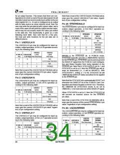
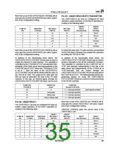
Pin 91: USER1/IRQ12/EXTCTS/EXINT188
The USER1/IRQ12 pin may be configured for input
operation, output operation, or ISA IRQ12 operation ac-
cording to the following table:
USER1/
IRQ12
Pin Direction
USER1/
IRQ12
Pin Data
PCMCIA
Pin
USER1EN
TCR14[1]
IRQ Select
PnPx70
IRQ Type
PnPx71
0
0
0
0
1
1
X
X
0
1
0
1
Ch
Ch
≠Ch
≠Ch
X
2h
1h
X
O
OD
I
IRQ12
IRQ12
NA
X
O
I
TIR29[1]
NA
X
X
X
O
TIR29[1]
Note that a read of the USERDT[1] bit (TIR29[1]) will al-
ways give the current USER1/IRQ12 pin value, regard-
less of pin configuration setting.
tocontrolthestartoftheTXstatemachine, providedthat
Am79C930 device firmware has enabled the operation
by setting the TXS bit of TIR8.
In addition to the functionality listed above, the
USER1/IRQ12/EXTCTS/EXINT188 pin may be used to
enable the internal TX state machine. This capability is
controlled by the CTSEN bit of TCR7 and operates inde-
pendently of the table above and independently of the
U1INTCNT bits of TCR7. When the CTSEN bit of TCR7
is set to 1, then the value of the USER1/IRQ12/
EXTCTS/EXINT188 pin will be ANDed with the value of
the TXS bit of TIR8. The output of the AND gate will
then be used to determine the start of the TX state
machine. In this way, an external signal, through the
USER1/IRQ12/EXTCTS/EXINT188 input, can be used
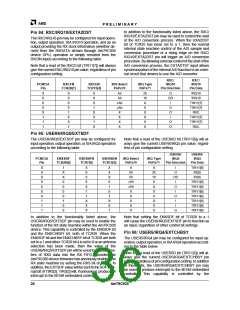
In addition to the functionality listed above, the
USER1/IRQ12/EXTCTS/EXINT188 pin may be used to
produce interrupts to the 80188 embedded controller.
This capability is controlled by the U1INTCNT bits of
TCR7 and operates independently of the bits in the
table above and independently of the CTSEN bit of
TCR7.Interrupts that are routed through the
USER1/IRQ12/EXTCTS/EXINT188 pin are indicated in
the U1INT bit of TCR11. The following table lists the pro-
gramming options for using the USER1/IRQ12/
EXTCTS/EXINT188 pin as a source of external interrupt
to the 80188 controller.
U1INTCNT
TCR7[4:3]
USER1 Pin
Event
U1INT Bit
Result (TCR11[3])
00
01
10
11
X
0 => interrupt disabled
1 => interrupt signalled
1 => interrupt signalled
1 => interrupt signalled
reset default condition
rising edge
falling edge
rising or falling edge
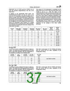
Note that a read of the USER7DL bit (TIR29[7]) will al-
ways give the current USER7/IRQ11 pin value, regard-
less of pin configuration setting.
Pin 92: USER7/IRQ11
The USER7/IRQ11 pin may be configured for input op-
eration, output operation, or ISA IRQ11 operation ac-
cording to the following table:
USER7DL (TIR29[7]) gives the current value of the
USER7/IRQ11 pin.
USER7/
USER7/
PCMCIA
Pin
USER7FN
TC30[7]
USER7EN
TCR14[7]
IRQ Select
PnPx70
IRQ Type
PnPx71
IRQ11
Pin Direction
IRQ11
Pin Data
0
0
0
0
1
1
1
0
0
0
1
0
0
1
X
X
X
X
0
Bh
Bh
≠Bh
X
2h
1h
X
O
IRQ11
IRQ11
NA
OD
I
I
X
NA
X
X
I
NA
1
X
X
O
I
TIR29[7]
NA
X
X
X
Am79C930
35

 AMD [ AMD ]