DC and Switching Characteristics
Bus Hold Specifications
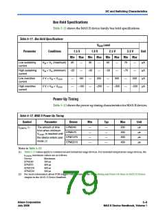
Table 5–11 shows the MAX II device family bus hold specifications.
Table 5–11. Bus Hold Specifications
VCCIO Level
1.8 V 2.5 V
Min Max Min Max Min Max Min Max
Parameter
Conditions
Unit
1.5 V
3.3 V
Low sustaining
current
VIN > VIL (maximum)
VIN < VIH (minimum)
0 V < VIN < VCCIO
0 V < VIN < VCCIO
20
–20
—
30
–30
—
50
–50
—
70
–70
—
µA
µA
µA
µA
—
—
—
—
High sustaining
current
—
—
—
—
Low overdrive
current
160
–160
200
–200
300
–300
500
–500
High overdrive
current
—
—
—
—
Power-Up Timing
Table 5–12 shows the power-up timing characteristics for MAX II devices.
Table 5–12. MAX II Power-Up Timing
Symbol
Parameter
Device
EPM240
EPM570
EPM1270
EPM2210
Min
—
Typ
—
Max
200
300
300
450
Unit
µs
The amount of time
from when minimum
CCINT is reached until
the device enters user
mode (2)
tCONFIG (1)
µs
—
—
V
µs
—
—
µs
—
—
Notes to Table 5–12:
(1) Table 5–12 values apply to commercial and industrial range devices. For extended temperature range devices, the
tCONFIG maximum values are as follows:
Device
Maximum
300 µs
400 µs
400 µs
500 µs
EPM240
EPM570
EPM1270
EPM2210
(2) For more information about POR trigger voltage, refer to the Hot Socketing and Power-On Reset in MAX II Devices
chapter in the MAX II Device Handbook.
Altera Corporation
July 2008
5–9
MAX II Device Handbook, Volume 1

 ALTERA [ ALTERA CORPORATION ]