Isolated, Digital Output, Power Monitoring IC
with Zero-Crossing Detection, Overcurrent and Overvoltage Flagging
ACS37800
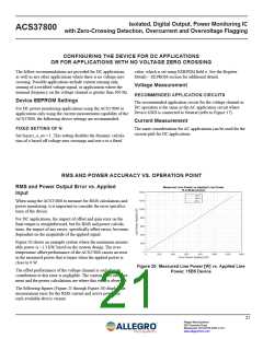
Another application circuit recommendation for the voltage chan- Additionally, the tolerance of the all resistors should be consid-
nel is shown in Figure 18. This is to be used in systems where ered when determining RSENSE. The minimum tolerance of the
the ACS37800 GND and the neutral terminal of the voltage input isolation resistors should be used along with the maximum toler-
are to be isolated. Here, RISO3 and RISO4 are added to the resistor
divider network.
ance of RSENSE.
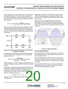
If the RSENSE is not sized appropriately, this can lead to the
voltage input to the ACS38700 exceeding the maximum input
range, which can cause the instantaneous voltage measurement to
saturate. This can lead to errors in the RMS calculations as shown
in Figure 19.
ꢅꢆꢄꢂꢆꢄ
ꢀ
= ꢀ
∗
ꢁꢂ
ꢃꢁ ꢂꢄ
ꢅꢁꢆꢇ1 + ꢅꢁꢆꢇ2 + ꢅꢁꢆꢇ3 + ꢅꢁꢆꢇ4 + ꢅꢆꢄꢂꢆꢄ
RISO1, RISO2, RISO3, and RISO4 should be equal and their value is
determined by the isolation requirements of the system. A value
of 1 MΩ is appropriate for many applications, but ultimately, the
resistance value used needs to comply with the required isolation
of the system.
Input > Fullscale
Output Saturation
RISO1
RISO2
VINP
1 MΩ
1 MΩ
Input Waveform
RSENSE
Output Readpoints
Vin
Absolute Output
Readpoints
RISO3
RISO4
VINN
1 MΩ
1 MΩ
Figure 19: Output Saturation
Figure 18: Voltage Channel Application; Device GND is
Current Measurement
Isolated from Neutral
For the current path, there are two current ranges to consider: the
range of RMS current to be measured and the range required for
overcurrent fault detection.
To determine the value of RSENSE required for a particular appli-
cation using either of the recommended circuits, the following
equation can be used:
When considering the range of RMS current to be measured, the
Current Sensing Range (IPR) is not to be exceeded. This can lead
to saturation, as shown in Figure 19, and lead to error in the RMS
calculations.
∆ꢄ
(
)
ꢅꢃꢆ ꢇꢈꢉ
ꢀꢁꢂꢃꢁꢂ
=
∗ ꢀꢅꢁꢋ
ꢄ
) − ∆ꢄ
(
(
)
ꢊꢅꢃꢂ ꢇꢈꢉ
ꢅꢃꢆ ꢇꢈꢉ
Where ΔVINR(MAX) = 250 mV, VLINE(MAX) is the maximum VLINE
voltage to be measured, and RISO is the sum of all of the isolation
resistors.
The overcurrent fault detection can exceed IPR and is defined as
Fault Range Max, IFAULT(MAX). Once the current exceeds IPR, the
RMS calculations will no longer be accurate.
If using the overvoltage detection functionality of the ACS37800,
this should be considering when determining the maximum VLINE
voltage to be measured. For example, in an application when
the nominal VLINE is equal to 120 VRMS and a 50% over-voltage
detection is required, VLINE(MAX) is:
120 VRMS × √2 × 1.5 = 255 V,
where the √2 is used to approximate the peak voltage assuming a
sinusoidal input.
20
Allegro MicroSystems
955 Perimeter Road
Manchester, NH 03103-3353 U.S.A.
www.allegromicro.com

 ALLEGRO [ ALLEGRO MICROSYSTEMS ]