Isolated, Digital Output, Power Monitoring IC
with Zero-Crossing Detection, Overcurrent and Overvoltage Flagging
ACS37800
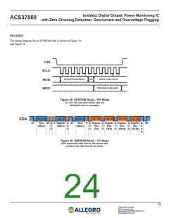
READING
The timing diagram for an EEPROM read is shown in Figure 29
and Figure 30.
CSN
SCLK
0
1
5
6
0
1
30
31
REGISTER ADDRESS
RW
WRITE DATA OR DC
MOSI
MISO
PREVIOUS CMD DATA
Figure 29: EEPROM Read – SPI Mode
For SPI, the read data will be sent out
during the above command.
SA[6:0]
A[6:0]
SA[6:0]
D[7:0]
D[7:0]
D[7:0]
D[7:0]
SDA
ST
ꢀlave W A 0 Reꢂisteꢁ A ST
ꢀlave R A Reꢂisteꢁ A Reꢂisteꢁ A Reꢂisteꢁ A Reꢂisteꢁ N SP
addꢁess
C
K
addꢁess C
addꢁess
C
K
Data
ꢃꢄꢅ0ꢆ
C
K
Data
ꢃ1ꢇꢅꢈꢆ
C
K
Data
ꢃꢉꢊꢅ1ꢋꢆ
C
K
Data
ꢃꢊ1ꢅꢉꢌꢆ
A
C
K
K
Figure 30: EEPROM Read – I2C Mode
Blue represents data sent by the master and
orange is the data sent by the slave.
24
Allegro MicroSystems
955 Perimeter Road
Manchester, NH 03103-3353 U.S.A.
www.allegromicro.com

 ALLEGRO [ ALLEGRO MICROSYSTEMS ]