Isolated, Digital Output, Power Monitoring IC
with Zero-Crossing Detection, Overcurrent and Overvoltage Flagging
ACS37800
DIGITAL COMMUNICATION
Communication Interfaces
Registers and EEPROM
The ACS37800 supports communication over 1 MHz I2C and
10 MHz SPI. However, the communication protocol is fixed dur-
ing factory programming. The ACS37800 MISO pin continues to
drive the MISO line when CS goes high. This may prevent other
devices from communicating properly. It is recommended that the
ACS37800 be the only device on the SPI bus if using SPI com-
munication.
WRITE ACCESS
The ACS37800 supports factory and customer EEPROM space as
well as volatile registers. The customer access code must be sent
prior to writing these customer EEPROM spaces. In addition, the
device includes a set of free space EEPROM registers that are
accessible with or without writing the access code.
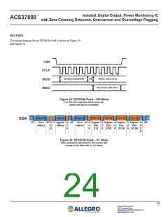
READ ACCESS
SPI
All EEPROM and volatile registers may be read at any time
regardless of the access code.
The SPI frame consists of:
• The Master writes on the MOSI line the 7-bit address of the
register to be read from or written to.
EEPROM
• The next bit on the MOSI line is the read/write (RW) indicator. At power up, all shadow registers are loaded from EEPROM,
A high state indicates a Read and a low state indicates a Write. including all configuration parameters. The shadow registers can
be written to in order to change the device behavior without hav-
• The device sends a 32-bit response on the MISO line. The
ing to perform an EEPROM write. Any changes made in shadow
contents correspond to the previous command.
memory are volatile and do not persist through a reset event.
• On the MOSI line, if the current command is a write, the
32 bits correspond to the Write data, and in the case of a read,
the data is ignored.
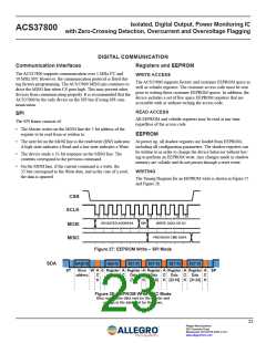
WRITING
The Timing Diagram for an EEPROM write is shown in Figure 27
and Figure 28.
CSN
SCLK
0
1
5
6
0
1
30
31
REGISTER ADDRESS
RW
WRITE DATA OR DC
MOSI
MISO
PREVIOUS CMD DATA
Figure 27: EEPROM Write – SPI Mode
SDA
SA[6:0]
A[6:0]
D[7:0]
D[7:0]
D[7:0]
D[7:0]
ST
ꢀlave W A 0 Reꢂisteꢁ A Reꢂisteꢁ A Reꢂisteꢁ A Reꢂisteꢁ A Reꢂisteꢁ A SP
addꢁess
C
K
addꢁess C Data
ꢃꢄꢅ0ꢆ
C
K
Data
ꢃ1ꢇꢅꢈꢆ
C
K
Data
ꢃꢉꢊꢅ1ꢋꢆ
C
K
Data
ꢃꢊ1ꢅꢉꢌꢆ
C
K
K
Figure 28: EEPROM Write – I2C Mode
Blue represents data sent by the master and
orange is the data sent by the slave.
23
Allegro MicroSystems
955 Perimeter Road
Manchester, NH 03103-3353 U.S.A.
www.allegromicro.com

 ALLEGRO [ ALLEGRO MICROSYSTEMS ]