Isolated, Digital Output, Power Monitoring IC
with Zero-Crossing Detection, Overcurrent and Overvoltage Flagging
ACS37800
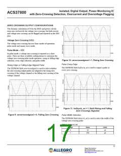
The current zero crossing has just one basic mode of operation:
pulse mode.
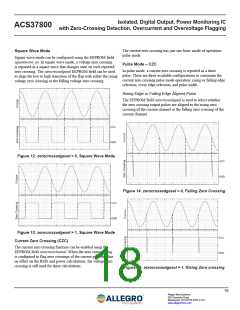
Square Wave Mode
Square wave mode can be configured using the EEPROM field
squarewave_en. In square wave mode, a voltage zero crossing
is reported as a square wave that changes state on each reported
zero crossing. The zerocrossedgesel EEPROM field can be used
to align the low to high transition of the flag with either the rising
voltage zero crossing or the falling voltage zero crossing.
Pulse Mode – CZC
In pulse mode, a current zero crossing is reported as a short
pulse. There are three available configurations to customize the
current zero crossing pulse mode operation: rising or falling edge
selection, every edge selection, and pulse width.
Rising Edge or Falling Edge Aligned Pulse
The EEPROM field zerocrossedgesel is used to select whether
the zero crossing output pulses are aligned to the rising zero
crossing of the current channel or the falling zero crossing of the
current channel.
Figure 12: zerocrossedgesel = 0, Square Wave Mode
Figure 14: zerocrossedgesel = 0, Falling Zero Crossing
Figure 13: zerocrossedgesel = 1, Square Wave Mode
Current Zero Crossing (CZC)
The current zero crossing function can be enabled using the
EEPROM field zerocrosschansel. When the zero crossing flag
is configured to flag zero crossings of the current path, this has
no effect on the RMS and power calculations; the voltage zero
crossing is still used for these calculations.
Figure 15: zerocrossedgesel = 1, Rising Zero crossing
18
Allegro MicroSystems
955 Perimeter Road
Manchester, NH 03103-3353 U.S.A.
www.allegromicro.com

 ALLEGRO [ ALLEGRO MICROSYSTEMS ]