Isolated, Digital Output, Power Monitoring IC
with Zero-Crossing Detection, Overcurrent and Overvoltage Flagging
ACS37800
ZERO CROSSING OUTPUT CONFIGURATIONS
The dynamic calculation of N for the RMS and power calcula-
tions uses exclusively the voltage zero crossing, but both current
and voltage zero crossing can be flagged and reported on the DIO
pins.
Voltage Zero Crossing (VZC)
The voltage zero crossing has two basic modes of operation,
pulse mode and square wave mode.
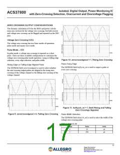
Pulse Mode – VZC
In pulse mode, a voltage zero crossing is reported as a short
pulse. There are three available configurations to customize the
voltage zero crossing pulse mode operation: rising or falling edge
selection, every edge selection, and pulse width.
Figure 10: zerocrossedgesel = 1, Rising Zero Crossing
Pulse Every Edge
Rising Edge or Falling Edge Aligned Pulse
The EEPROM field halfcycle_en is used to output a pulse at
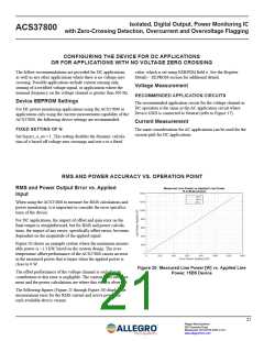
every zero crossing.
The EEPROM field zerocrossedgesel is used to select whether
the zero crossing output pulses are aligned to the rising zero
crossing of the voltage channel or the falling zero crossing of the
voltage channel.
Figure 11: halfcycle_en = 1, Both Rising and Falling
Zero Crossings Signaled
Figure 9: zerocrossedgesel = 0, Falling Zero Crossing
Pulse Width Selection
The EEPROM field delaycnt_sel is used to select the width of the
voltage zero crossing pulse.
Table 1: delaycnt_sel
Range
Value
32
Units
µs
0
1
256
µs
17
Allegro MicroSystems
955 Perimeter Road
Manchester, NH 03103-3353 U.S.A.
www.allegromicro.com

 ALLEGRO [ ALLEGRO MICROSYSTEMS ]