Isolated, Digital Output, Power Monitoring IC
with Zero-Crossing Detection, Overcurrent and Overvoltage Flagging
ACS37800
POWER FACTOR
Power Calculations
The magnitude of the ratio of the real power to apparent power,
calculated at the end of each cycle is:
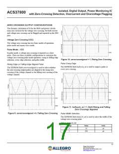
VOLTAGE ZERO CROSSING
The RMS and power calculations of the ACS37800 are calcu-
lated over a window of N samples. By default, this window is
calculated dynamically based on the zero crossings of the voltage
signal. A rising voltage zero crossing triggers the start of a new
window. N then increases with each 32 kHz sample until the next
rising voltage zero crossing, recording the current and voltage
readings at each sample. This ends the calculation window, and
all RMS and power calculations are performed on the saved data.
During this time, the next calculation window is started.
PACTIVE
|PF| =
|S|
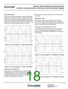
LEADING OR LAGGING POWER FACTOR
The current leading or lagging the voltage is communicated as a
single bit, posangle. This bit represents the sign of the reactive
power. The sign of the reactive power is determined by compar-
ing the timing of the zero crossings of the current and voltage. As
such, it is only meaningful in the case of a linear load.
Voltage zero crossings are detected with time-based hysteresis
that removes the possibility of noise causing multiple zero cross-
ings to be reported at each true zero crossing.
The sign of the reactive power, posangle, along with the sign of
the power factor, pospf, can be used to determine whether the
load is inductive or capacitive, as well as whether power is being
generated or consumed. This is shown in the four-quadrant figure
below (refer to Figure 6).
IRMS AND VRMS
The cycle-by-cycle calculation of the root mean square of both
the current and voltage channels is:
n = N – 1 In
∑
n = N – 1Vn
2
2
∑
n = 0
n = 0
POSPF = 0
POSANG = 0
POSPF = 1
POSANG = 1
IRMS
=
VRMS =
N
N
Capacitive and
Generating
Inductive and
Consuming
where In (icodes) and Vn (vcodes) are the instantaneous measure-
ments of current and voltage, respectively.
Lagging
Leading
Real
APPARENT POWER
The magnitude of the complex power being measured; calculated
at the end of each cycle is:
POSPF = 0
POSANG = 1
POSPF = 1
POSANG = 0
|S| = IRMS × VRMS
Inductive and
Generating
Capacitive and
Consuming
ACTIVE POWER
The real component of power being measured, calculated cycle
by cycle is:
Figure 6: Four Quadrant, Power Factor
∑
n = N – 1 Pn
n = 0
PACTIVE
=
Pn = In × Vn
N
REACTIVE POWER
The imaginary component of power being measured, calculated
at the end of each cycle is:
ꢀ ꢄ ꢂ 2 ꢅ ꢃ 2
2
ꢀ ꢁ ꢂ2 ꢃ ꢄꢅCꢆIꢇꢈ
Ф
Actiꢁe Power, ꢂ = ꢁI cosФ
Figure 7: Power Triangle
14
Allegro MicroSystems
955 Perimeter Road
Manchester, NH 03103-3353 U.S.A.
www.allegromicro.com

 ALLEGRO [ ALLEGRO MICROSYSTEMS ]