Isolated, Digital Output, Power Monitoring IC
with Zero-Crossing Detection, Overcurrent and Overvoltage Flagging
ACS37800
THEORY OF OPERATION
current and voltage measurements are stored in the icodes and
vcodes fields. The instantaneous apparent power, which is the
product of icodes and vcodes, is stored in the field pinstant.
Introduction
The ACS37800 provides a simple solution for voltage, current,
and power monitoring in 60 Hz AC and DC applications and is
particularly well suited for high isolation. The voltage is mea-
sured by resistor dividing it down to fit the input range of the
on-board voltage sense amplifier, as well as to add isolation.
The current is measured using the integrated current loop and
galvanically isolated Hall sensor. Both analog signals are then
sampled using high accuracy ADCs before entering the digital
system. Here, the metrology engine is used to determine fre-
quency, calculate RMS values of current, voltage, and power, as
well as provide a range of averaging and configuration options.
One can choose to read out all the different information provided
using SPI or I2C. When using I2C, there are also options for
using some of the digital I/O pins for overcurrent or zero cross-
ing detection. Overall, with a high degree of configurability and
integrated features, the ACS37800 can fit most power monitoring
applications. The following sections will help explain in more
detail these features and configuration options, as well as how to
best use the ACS37800 for particular applications.
Overcurrent Measurement Path
A separate filter on the current ADC is used to create a lower
resolution but higher bandwidth sample rate measurement of the
current to be used for overcurrent detection. This filter outputs a
12-bit word at a 1 MHz update rate and 200 kHz bandwidth. The
overcurrent fault logic compares this auxiliary current value to the
user-defined overcurrent fault threshold, defined by the field fault.
It is important to note that the trim for the main 16-bit current path
is also applied to the overcurrent path, such that the overcurrent
fault has the same level of accuracy as the main signal path.
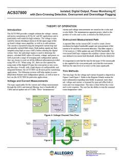
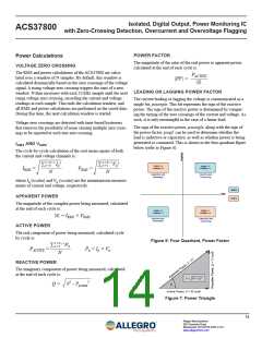
Trim Methods
The trim logic for the voltage and current channels is depicted in
Figure 4 and Figure 5. Refer to the Register Details section for
more information regarding trim fields. In general, each chan-
nel, voltage and current, is trimmed for gain and offset both at
room and over temperature. This trim is done before the icodes
and vcodes registers. The user has the ability to trim the nominal
room temperature value.
Voltage and Current Measurements
The main signal paths for the current and voltage measurement,
through the ADCs and internal filtering, have a bandwidth of
1 kHz and an update rate of 32 kHz. These “instantaneous”
Gain Trim
Delay
Offset Trim
Satura�on
adc_out_v
Z-x
+
+
vcodes
VchanGainSel
ichan_del_en
vchan_offset_code
+
+
Factory
Trim
chan_del_sel
vqvo_tc
Figure 4: Voltage Channel Trim Flow
Delay
Offset Trim
Gain Trim
Satura�on
adc_out_i
Z-x
+
+
icodes
ichan_del_en
qvo_fine
+
+
sns_fine
qvo_tc
chan_del_sel
Factory
Trim
sns_tc
Figure 5: Current Channel Trim Flow
13
Allegro MicroSystems
955 Perimeter Road
Manchester, NH 03103-3353 U.S.A.
www.allegromicro.com

 ALLEGRO [ ALLEGRO MICROSYSTEMS ]