[AK4679]
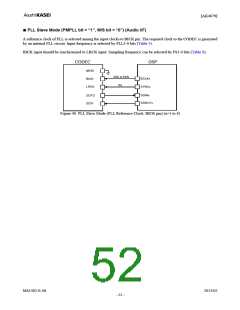
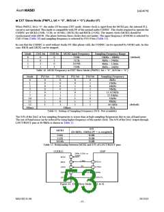
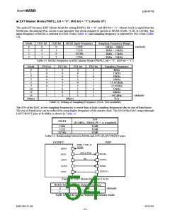
■ Audio Interface Format
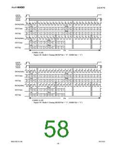
Four types of data formats are available and can be selected by setting the DIF1-0 bits (Table 18). In all modes, the serial
data is MSB first, 2’s complement format. Audio interface formats can be used in both master and slave modes. LRCK
and BICK are output from the audio I/F in master mode, but must be input to the audio I/F in slave mode.
DIF1
bit
DIF0
bit
Mode
SDTO (ADC)
SDTI (DAC)
BICK
Figure
0
1
0
0
0
1
16bit DSP Mode
24bit MSB justified 16bit LSB justified
16bit DSP Mode
Table 19
Figure 50
≥ 32fs
≥ 32fs
24bit MSB
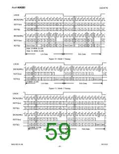
2
3
1
1
0
1
24bit MSB justified
Figure 51 (default)
Figure 52
≥ 48fs
justified
24/16 bit I2S
compatible
24/16bit I2S
compatible
32fs or
≥ 48fs
Table 18. Audio Interface Format
If 24-bit(16-bit) data that ADC outputs is converted to 8-bit data by removing LSB 16-bit(8-bit), “−1” at 24bit(16bit) data
is converted to “−1” at 8-bit data. And when the DAC playbacks this 8-bit data, “−1” at 8-bit data will be converted to
“−65536” at 24-bit (“−256” at 16-bit) data which is a large offset. This offset can be removed by adding the offset of
“32768” at 24-bit (“128” at 16bit) to 24-bit(16-bit) data before converting to 8-bit data.
In Mode 1, 2 and 3, the SDTO is clocked out on the falling edge (“↓”) of BICK and the SDTI is latched on the rising edge
(“↑”).
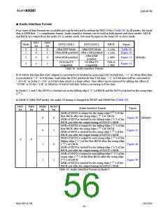
In Mode 0 (16bit DSP mode), the audio I/F timing is changed by BCKP and MSBS bits (Table 19).
DIF1
bit
DIF0
bit
MSBS BCKP
Audio Interface Format
Figure
bit
bit
MSB of SDTO is output by the rising edge (“↑”) of the
first BICK after the rising edge (“↑”) of LRCK.
MSB of SDTI is latched by the falling edge (“↓”) of the
BICK just after the output timing of SDTO’s MSB.
MSB of SDTO is output by the falling edge (“↓”) of the
first BICK after the rising edge (“↑”) of LRCK.
MSB of SDTI is latched by the rising edge (“↑”) of the
BICK just after the output timing of SDTO’s MSB.
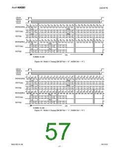
MSB of SDTO is output by next rising edge (“↑”) of the
falling edge (“↓”) of the first BICK after the rising edge
(“↑”) of LRCK.
0
0
Figure 46 (default)
0
1
1
0
Figure 47
0
0
Figure 48
MSB of SDTI is latched by the falling edge (“↓”) of the
BICK just after the output timing of SDTO’s MSB.
MSB of SDTO is output by next falling edge (“↓”) of the
rising edge (“↑”) of the first BICK after the rising edge
(“↑”) of LRCK. Figure 49
1
1
MSB of SDTI is latched by the rising edge (“↑”) of the
BICK just after the output timing of SDTO’s MSB.
Table 19. Audio Interface Format in Mode 0
MS1402-E-06
2013/02
- 56 -

 AKM [ ASAHI KASEI MICROSYSTEMS ]