Ambassador T8100A, T8102, and T8105
H.100/H.110 Interfaces and Time-Slot Interchangers
Advance Data Sheet
November 1999
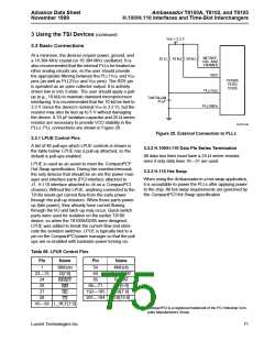
3 Using the TSI Devices (continued)
VDD = 3.3 V
3.3 Basic Connections
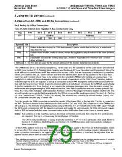
At a minimum, the devices require power, ground, and
a 16.384 MHz crystal (or 16.384 MHz oscillator). It is
also recommended that the internal PLLs be treated as
other analog circuits are, so the user should provide
the appropriate filtering between the PLL1VDD and VDD
pins (as well as PLL2VDD and VDD pins). The RDY pin
is operated as an open collector output. It is actively
driven low or into 3-state. The user should apply a pull-
up (e.g., 10 kΩ) to maintain standard microprocessor
interfacing. It is recommended that the 10 kΩ be tied to
3.3 V (since the device’s nominal VOH is 3.3 V), but the
resistor may also be tied up to 5 V without damaging
the device. A 33 µF tantalum capacitor and 25 Ω series
resistor are necessary to provide VCO stability in the
PLLs. PLL connections are shown in Figure 20.
NETREF,
C8s, AND
FRAMES
25 Ω
10 kΩ 50 kΩ
RDY
PLLVDDS
PLLGNDS
T8100A
T8102
T8105
TANTALUM
33 µF
5-6114.aF
Figure 20. External Connection to PLLs
3.3.1 LPUE Control Pins
A list of 46 pull-ups which LPUE controls is shown in
the table below. LPUE has a pull-up attached, so the
default is pull-ups enabled.
3.3.2 H.100/H.110 Data Pin Series Termination
All data bus lines must have a 24 Ω series resistor,
even if only data lines 16—31 are used.
LPUE is used as an assist to meet the CompactPCI*
Hot Swap specification. During live insertion/removal,
the only devices that should be on are the power man-
ager and interface parts (PCI interface attached to
J1, H.110 interface attached to J4 on a CompactPCI
chassis). Without the LPUE, anything connected to the
T810x would get current flow from the early power
through the pull-up resistors. When those parts power-
up (late power), they already have current flowing
through the I/O and latch-up may occur. Quick-switch
parts were used for isolation on the earlier T8100
device, so when the T8100A/02/05 were designed,
LPUE was added to break the current flow and elimi-
nate the isolation switches. LPUE is typically tied to a
pin on the CompactPCI power manager so that the pull
ups are re-enabled with backside power turning on.
3.3.3 H.110 Hot Swap
When using the Ambassador in a hot-swap application,
it is acceptable to power the PLLs after applying power
to the chip. All hot-swap requirements are governed by
the CompactPCI Hot Swap specification.
Table 68. LPUE Control Pins
Pin
Name
Pin
Name
1
3MHzIn
D[7:0]
54
64
65
4MHzIn
FromDJAT
ToDJAT
22 15
—
24
26
27
28
RESET
WR
66 71
GP[5:0]
—
192 185
LDI[7:0]
LDI[15:8]
—
RD
201 194
—
CS
45 38 L_REF[7:0]
—
* CompactPCI is a registered trademark of the PCI Industrial Com-
puter Manufacturers Group.
Lucent Technologies Inc.
71

 AGERE [ AGERE SYSTEMS ]