Ambassador T8100A, T8102, and T8105
H.100/H.110 Interfaces and Time-Slot Interchangers
Advance Data Sheet
November 1999
3.3.6 PC Board BGA Considerations
3 Using the TSI Devices (continued)
There are no special requirements for the thermal balls
on the BGA package when designing a printed-circuit
board.
3.3 Basic Connections (continued)
3.3.4 Physical Connections for H.100
All H.100 bus signals must adhere to the specification,
ECTF H.100 Hardware Compatibility Specification: CT
Bus. The H.100 clock signals, CT_C8_A, CT_C8_B,
/CT_FRAME_A, /CT_FRAME_B, and CT_NETREF,
each require an individual external pull-up of 100 kΩ to
5 V or 50 kΩ to 3.3 V.
CT_FRAMEA
CT_FRAMEA
33 Ω
10 kΩ
LUCENT
T8100A
T8102
T8105
CTC8A_SRC
CT_C8A
CT_C8A
33 Ω
If CT_NETREF, CT_8A, CT_8B, CT_FRAME_A, or
CT_FRAME_B are not going to be used, they must be
tied to ground, VCC or a pull-up resistor. They cannot be
left floating, since they could oscillate.
10 kΩ
CTC8A_SRC
CT_FRAMEB
CT_FRAMEB
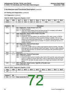
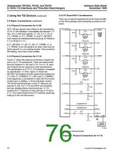
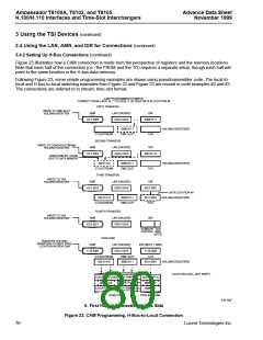
3.3.5 Physical Connections for H.110
33 Ω
10 kΩ
Figure 21 shows the physical connections required for
use in an H.110 environment. There are electrical dif-
ferences between H.100 and H.110. For H.110, exter-
nal components are required to meet specifications.
The specification is ECTF H.110 Hardware Compatibil-
ity Specification: CT Bus. Figure 21 shows the
CTC8B_SRC
CT_C8B
CT_C8B
33 Ω
10 kΩ
NETREF terminations and the required terminations for
CT_C8A, CT_FRAMEA, CT_C8B, and CT_FRAMEB.
Each signal has a mechanism to short the 33 Ω series
resistor and, in addition, a 10 kΩ pull-down resistor.
The 50 kΩ internal pull-ups on the CT data bus are
used for H.100. For H.110, the DPUE pin should be
tied low, disabling these internal pull-ups. H.110
requires the CT data bus to have pull-ups of 18 kΩ to
0.7 V. The control leads of the FET switches would typ-
ically go to the microprocessor.
CTC8B_SRC
24 Ω
CT_NETREF2
CT_NETREF1
CT_NETREF2
CT_NETREF1
18 kΩ
0.7 V
24 Ω
18 kΩ
0.7 V
0 Ω DEPOPULATE
0 Ω DEPOPULATE
24 Ω
SCLK
SCLKX2
SCLK
SCLKX2
32
CTD[0:31]
CTD[0:31]
DPUE
LPUE*
18 kΩ
0.7 V
POWER
MANAGER
5-7142cF
* Switched low for insertion/removal.
Figure 21. Physical Connections for H.110
72
Lucent Technologies Inc.

 AGERE [ AGERE SYSTEMS ]