Ambassador T8100A, T8102, and T8105
H.100/H.110 Interfaces and Time-Slot Interchangers
Advance Data Sheet
November 1999
3 Using the TSI Devices (continued)
3.4 Using the LAR, AMR, and IDR for Connections (continued)
3.4.1 Setting Up Local Connections (T8100A, T8105 Only) (continued)
Table 70. IDR: Indirect Data Register, Local Connections Only
The second transfer requires that data in the IDR be defined as follows.
Reg
R/W
Bit 7
Bit 6
Bit 5
Bit 4
Bit 3
Bit 2
Bit 1
Bit 0
IDR
R/W
Control
Address
XCS
PME
FME
CHE
Symbol
Bit
Description
XCS
7
A programmable bit which is routed to the XCS pin one time slot prior to the data to
which it relates.
PME
FME
6
5
4
A high enables the pattern mode; the lower 8 bits of the connection address (time slot
and stream LSB) is routed to the time slot instead of data.
A high enables the use of the alternate data buffer. (Refer to Appendix B for minimum
and constant delay settings.)
CHE
Enables the time-slot connection; a low in this bit forces 3-state during the time slot.
Address
3—0 All 4 bits are used for the stream address of the desired data memory location.
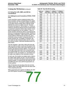
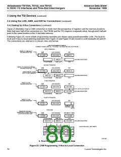
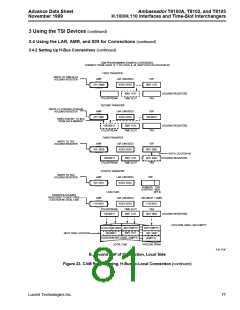
After the second transfer is made, the entire 15 bits will be loaded into the connection memory; i.e., the second
transfer triggers the actual memory access. Figure 22 shows how the connections are made from the perspective
of the registers and memory contents.
If the user wishes to set up a pattern mode connection, then the first transfer is a full 8 bits (i.e., the pattern), rather
than the 7-bit time-slot value. This pattern byte will be stored in the lowest 8 bits of the selected connection memory
location. The pattern byte will be sent instead of a byte from local data memory during the output stream and time
slot which corresponds to the connection memory location.
LOCAL MEMORY PROGRAMMING EXAMPLE: CONNECT FROM 14, 7 TO 3, 29 (STREAM, TIME SLOT)
FIRST TRANSFER:
SECOND TRANSFER:
WRITE TO
WRITE TO
TIME-SLOT
FIELD IN
CONTROL/STREAM
AMR
0101 0011
LAR
IDR
FIELD IN
AMR
0100 0011
LAR
IDR
CONNECTION
MEMORY
CONNECTION
0001 1101
0001 1110
0001 1101
0000 0111
MEMORY
3, 27
3, 27
3, 28
3, 29
3, 30
3, 31
3, 28
3, 29
3, 30
3, 31
0001
1110
0000 0111
0000 0111
CONNECTION
MEMORY
CONNECTION
MEMORY
5-6115aF
Figure 22. Local-to-Local Connection Programming (T8100A, T8105 Only)
74
Lucent Technologies Inc.

 AGERE [ AGERE SYSTEMS ]